
Service Manual

SERVICING
83
S-1 CHECKING VOLTAGE
1. Remove outer case, control panel cover, etc., from unit being
tested.
With power ON:
Line Voltage now present.
WARNING
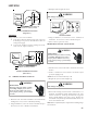
2. Using a voltmeter, measure the voltage across terminals L1
and L2 of the contactor for the condensing unit or at the field
connections for the air handler or heaters.
3. No reading - indicates open wiring, open fuse(s) no power or
etc., from unit to fused disconnect service. Repair as needed.
4. With ample voltage at line voltage connectors, energize the
unit.
5. Measure the voltage with the unit starting and operating, and
determine the unit Locked Rotor Voltage. NOTE: If checking
heaters, be sure all heating elements are energized.
Locked Rotor Voltage is the actual voltage available at the
compressor during starting, locked rotor, or a stalled condi-
tion. Measured voltage should be above minimum listed in
chart below.
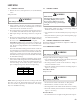
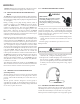
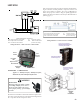
To measure Locked Rotor Voltage attach a voltmeter to the run
"R" and common "C" terminals of the compressor, or to the T
1
and T
2
terminals of the contactor. Start the unit and allow the
compressor to run for several seconds, then shut down the
unit. Immediately attempt to restart the unit while measuring
the Locked Rotor Voltage.
6. Locked rotor voltage should read within the voltage tabula-
tion as shown. If the voltage falls below the minimum voltage,
check the line wire size. Long runs of undersized wire can
cause low voltage. If wire size is adequate, notify the local
power company in regard to either low or high voltage.
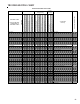
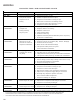
Unit Supply Voltage
Voltage Min. Max
208/230 197 253
460 414 506
NOTE: When operating electric heaters on voltages other than
240 volts, refer to the System Operation section on electric
heaters to calculate temperature rise and air flow. Low voltage
may cause insufficient heating.
S-2 CHECKING WIRING
WARNING
HIGH VOLTAGE!
Disconnect ALL power before servicing
or installing. Multiple power sources
may be present. Failure to do so may
cause property damage, personal injury
or death.
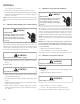
1. Check wiring visually for signs of overheating, damaged
insulation and loose connections.
2. Use an ohmmeter to check continuity of any suspected open
wires.
3. If any wires must be replaced, replace with comparable gauge
and insulation thickness.
S-3 CHECKING THERMOSTAT AND WIRING
Thermostat Wiring: The maximum wire length for 18 AWG ther-
mostat wire is 100 feet.
S-3A THERMOSTAT WIRING
Line Voltage now present.
WARNING
With power ON, thermostat calling for cooling
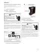
1. Use a voltmeter to check for 24 volts at thermostat wires C and
Y in the condensing unit control panel.
2. No voltage indicates trouble in the thermostat, wiring or
external transformer source.
3. Check the continuity of the thermostat and wiring. Repair or
replace as necessary.
Indoor Blower Motor
With power ON:
Line Voltage now present.
WARNING
1. Set fan selector switch at thermostat to "ON" position.
2. With voltmeter, check for 24 volts at wires C and G.
3. No voltage indicates the trouble is in the thermostat or wiring.
4. Check the continuity of the thermostat and wiring. Repair or
replace as necessary.
Resistance Heaters
1. Set room thermostat to a higher setting than room tempera-