
ARUF Installation Manual


10
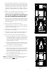
LIQUID PRESSURE
PSIG R-22 R-410A
200 101 70
210 105 73
220 108 76
225 110 78
235 113 80
245 116 83
255 119 85
265 121 88
275 124 90
285 127 92
295 130 95
305 133 97
325 137 101
355 144 108
375 148 112
405 155 118
415 157 119
425 n/a 121
435 n/a 123
445 n/a 125
475 n/a 130
500 n/a 134
525 n/a 138
550 n/a 142
575 n/a 145
600 n/a 149
625 n/a 152
SATURATED LIQUID PRESSURE
TEM PERATURE CHART
SATURATED LIQUID
TEM PERATURE ºF
NOTE: Unit s mat ched wit h indoor coils equipped wit h non-
adj ust able TXV should be charged by subcooling only.
8 Condensate Drain Lines
The coil drain pan has a primary and a secondary drain wit h
3/ 4" NPT f emale connect ions. The connect ors required are
3/ 4" NPT mal e, eit her PVC or met al pipe, and should be
hand t ight ened t o a t orque of no more t han 37 in-lbs. t o
prevent damage t o t he drain pan connect ion. An insert ion
dept h of approximat ely 3/ 8” t o 1/ 2” (3-5 t urns) should be
expect ed at t his t orque.
1. Ensure drain pan hole is not obst ruct ed.
2. To prevent pot ent ial sweat ing and dripping on t o f in-
ished space, it may be necessary t o insulat e t he con-
densat e drain l ine locat ed inside t he building. Use
Armaf lex
®
or similar mat erial .
A secondary condensat e drain connect ion has been provided
for areas where t he building codes require it . Pit ch all drain
lines a minimum of 1/ 4" per f oot t o provide f ree drainage.
Provide required support t o t he drain line t o prevent bowing.
If t he secondary drain line is required, run t he line separat ely
from t he primary drain and end it where condensat e discharge
can be easily seen.
NOTE: Wat er coming f rom secondary line means t he coil pri-
mary drain is plugged and needs immediat e at t ent ion.
CAUTION
If secondary drain is not installed, the secondary
access must be plugged.
Insulat e drain lines locat ed inside t he buil ding or above a
finished living space t o prevent sweat ing. Inst all a conden-
sat e t rap t o ensure proper drainage.
NOTE: When unit s are inst alled above ceilings, or in ot her
locat ions where damage f rom condensat e overf low may
occur, it is MANDATORY t o i nst al l a f i el d f abri cat ed auxi li ary
drain pan under t he coil cabinet enclosure.
The inst allat ion must include a “ P” st yle t rap t hat is lo-
cat ed as close as is pract ical t o t he evaporat or coil. See
Figure 12 f or det ails of a t ypical condensat e line “ P” t rap.
NOTE: Unit s operat ing in high st at ic pressure applicat ions
may require a deeper f ield const ruct ed “ P” st yle t rap t han
is shown in Figure 12 t o allow proper drainage and prevent
condensat e overf low.
Air Handler
3" MIN.
POSITIVE LIQUID
SEAL REQUIRED
AT TRAP
Drain
Connection
2" MIN.
Figure 12
NOTE: Trapped lines are required by many local codes. In
t he absence of any prevailing local codes, please refer t o
t he requirement s list ed in t he
Uniform Mechanical Building
Code.
A drain t rap in a draw-through applicat ion prevent s air f rom
being drawn back t hrough t he drain line during f an opera-
t ion t hus prevent ing condensat e f rom draining, and if con-
nect ed t o a sewer line t o prevent sewer gases f rom being
drawn int o t he airst ream during blower operat ion.
Use of a condensat e removal pump is permit t ed when nec-
essary. This condensat e pump should have provisions f or
shut t ing of f t he cont rol volt age should a blocked drain oc-
cur. A t rap must be inst alled bet ween t he unit and t he con-
densat e pump.
IMPORTANT NOTE: The evaporat or coil is f abricat ed wit h
oils t hat may dissolve st yrof oam and cert ain t ypes of plast ics.
Theref ore, a removal pump or f loat swit ch must not cont ain
any of t hese mat erials.