
ARUF Installation Manual


11
Tip: Priming t he “ P” t rap may avoid improper draining at t he
init ial inst allat ion and at t he beginning of t he cooling season.
9 Ductwork
This air handler is designed f or a complet e supply and ret urn
duct work syst em.
Do not operate this product without all the ductwork
attached.
To ensure correct syst em perf ormance, t he duct work is t o
be sized t o accommodat e 350-450 CFM per t on of cooling
wit h t he st at ic pressure not t o exceed 0.5" in w. c. Ref er t o
ACCA Manual D, Manual S and Manual RS for inf ormat ion on
duct sizing and applicat ion. Flame ret ardant duct work is
t o be used and sealed t o t he unit in a manner t hat will
prevent leakage.
NOTE: A downf low applicat ion wit h elect ric heat must have
an L-shaped sheet met al supply duct wit hout any out let s or
regist ers locat ed direct ly below t he heat er.
9.1 Ret urn Ductwork
DO NOT LOCATE THE RETURN DUCTWORK IN AN AREA
THAT CAN INTRODUCE TOXIC, OR OBJECTIONABLE
FUMES/ ODORS INTO THE DUCTWORK. The ret urn
duct work is t o be connect ed t o t he air handler bot -
t om (upf low conf igurat ion).
10 Return Air Filters
Each inst allat ion must include a ret urn air f ilt er. This f il-
t ering may be perf ormed at t he air handler using t he f ac-
t ory f ilt er rails or ext ernally such as a ret urn air f ilt er grille.
When using t he f act ory f ilt er rails, a nominal 16x20x1” ,
20x20x1” or 24x20x1” (act ual dimension must be less t han
23-½” x20” ) f ilt er can be inst alled on a B, C and D cabinet
respect ively (t he cabinet size is t he sevent h let t er of t he
model number).
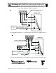
11 Electric Heat
Ref er t o t he inst allat ion manual provided wit h t he elect ric
heat kit f or t he correct inst allat ion procedure. All elect ric
heat must be f iel d inst alled. If inst alling t his opt ion, t he
ONLY heat kit s t hat are permit t ed t o be used are t he HKS
series. Ref er t o t he air handler unit ’ s Serial and Rat ing plat e
or t he HKS specif icat ion sheet s t o det ermine t he heat kit s
compat ible wit h a given air handler. No ot her accessory
heat kit besides t he HKS series may be inst alled in t hese air
handlers.
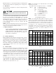
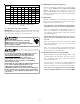
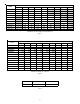
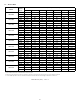
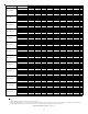
The heat ing mode t emperat ure rise is dependent upon t he
syst em airf low, t he supply volt age, and t he heat kit size
(kW) select ed. Use dat a provided in Tables 4, 5, AND 6 t o
det ermine t he t emperat ure rise (° F).
NOTE: For inst allat ions not indicat ed above t he f ollowing
formula is t o be used:
TR = (kW x 3412) x (Volt age Correct ion) / (1. 08XCFM)
Where: TR = Temperat ure Rise
kW = Heat er Kit Act ual kW
3412 = Bt u per kW
VC* = . 96 (230 Suppl y Volt s)
= . 92 (220 Suppl y Volt s)
= . 87 (208 Suppl y Volt s)
1.08 = Constant
CFM = Measured Airflow
*VC (Voltage Correction)
NOTE: The Temperat ure Rise Tables can also be used t o
est imat e t he air handler airf low delivery. When using t hese
t ables f or t his purpose set t he room t hermost at t o maximum
heat and allow t he syst em t o reach st eady st at e condit ions.
Insert t wo t hermomet ers, one in t he ret urn air and one in
t he supply air. The t emperat ure rise is t he supply air
t emperat ure minus t he room air t emperat ure. Using t he
t emperat ure rise calculat ed, CFM can be est imat ed f rom
t he TR f ormula above. See Service Manual f or more
inf ormat ion.
3568101519/2025
800 1219233137
1000 9 1519253044
1200 8 1215212537 49 62
1400 7 1113182132 42 53
1600 6 9 12 15 19 28 37 46
1800 5 8 10 14 16 25 33 41
2000 5 7 9 12 15 22 30 37
CFM
HEAT KIT NOMINAL kW
230/ 1/ 60 SUPPLY VOLTAGE - TEMP. RISE ° F
Table 4
3568101519/2025
800 1118223035
1000 9 14 18 24 28 42
1200 7 12 15 20 24 35 47 59
1400 6 10 13 17 20 30 40 51
1600 6 9 11151827 35 44
1800 5 8 10131624 31 39
2000 4 7 9 12 14 21 28 35
CFM
HEAT KIT NOMINAL kW
220/ 1/ 60 SUPPLY VOLTAGE - TEMP. RISE ° F
Table 5