
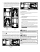
AVPTC Installation Instructions ComfortBridge


10
NOTE: The Temperature Rise Tables can also be used to esmate
the air handler airow delivery. When using these tables for this
purpose set the room thermostat to maximum heat and allow the
system to reach steady state condions. Insert two thermometers,
one in the return air and one in the supply air. The temperature
rise is the supply air temperature minus the return air temperature.
Using the temperature rise calculated, CFM can be esmated from
the TR formula above. See Spec Sheets and/or Service Manual for
more informaon.
13 Electrical and Control Wiring
IMPORTANT: All roung of electrical wiring must be made through
provided electrical knockouts. Do not cut, puncture or alter the
cabinet for electrical wiring.
13.1 BuildingElectricalServiceInspecon
This unit is designed for single-phase electrical supply only.
DO NOT OPERATE ON A THREE-PHASE POWER SUPPLY. Mea-
sure the power supply to the unit. The supply voltage must
be measured and be in agreement with the unit nameplate
power requirements and within the range shown.
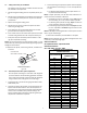
Nominal Input Minimum Voltage Maximum Voltage
208-240 197 253
ELECTRICAL VOLTAGE
Table 7
13.2 WireSizing
Wire size is important to the operaon of your equipment.
Use the following check list when selecng the appropriate
wire size for your unit.
FIRE HAZARD!
To avoid the risk of property damage, personal injury
or fire, use only copper conductors.
HIGH VOLTAGE!
Failure to do so may cause property damage,
personal injury or death.
Disconnect ALL power before servicing.
Multiple power sources may be present.
HIGH VOLTAGE!
To avoid property damage, personal injury or death
due to electrical shock, this unit MUST have an
electrical ground. The
electrical ground circuit may consist of an
appropriately sized electrical wire connecting the
ground lug in the unit control box to the building
electrical service panel.
Other methods of grounding are permitted if performed
in accordance with the National Electric Code
(NEC)/American National Standards Institute
(ANSI)/National Fire Protection Association (NFPA) 70
and local/state codes. In Canada, electrical grounding
is to be in accordance with the Canadian Electric Code
(CSA) C22.1.
uninterrupted, unbroken
• WireusedmustcarrytheMinimumCircuitAmpacity(MCA)
listedontheunit’sSeriesandRangPlate.
• Refer to the NEC (USA) or CSA (Canada) for wire sizing. The
unit MCA for the air handler and the oponal electric heat
kit can be found on the unit Series and Rang Plate.
• Wiremustbesizedtoallownomorethana2%voltage
dropfromthebuildingbreaker/fusepaneltotheunit.
• Wires with dierent insulaon temperature rang have
varying ampacies - be sure to check the temperature rang
used.
Refer to the latest edion of the Naonal Electric Code or in
Canada the Canadian Electric Code when determining the
correct wire size.
13.3 MaximumOvercurrentProtecon(MOP)
Every installaon must include an NEC (USA) or CEC (Canada)
approved overcurrent protecon device. Also, check with
local or state codes for any special regional requirements.
Protecon can be in the form of fusing or HACR style circuit
breakers. The Series and Rang Plate provides the maximum
overcurrent device permissible.
NOTE: Fuses or circuit breakers are to be sized larger than
the equipment MCA but not to exceed the MOP.
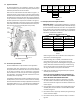
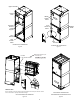
13.4 ElectricalConnecons–SupplyVoltage
IMPORTANT NOTE: USE COPPER CONDUCTORS ONLY.
Knockouts are provided on the air handler top panel and
sides of the cabinet to allow for the entry of the supply volt-
age conductors, as shown in Figure 13. If the knockouts on
the cabinet sides are used for electrical conduit, an adapter
ring must be used in order to meet UL1995 safety require-
ments. An NEC or CEC approved strain relief is to be used
at this entry point. Some codes/municipalies require the
supply wire to be enclosed in conduit. Consult your local
codes.
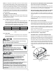
Side of
Cabinet
Top of
Cabinet
KNOCK-OUT FOR ELECTRICAL CONNECTIONS
Figure 12