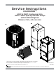
Service Instructions ComfortNet™ ASXC & DSXC Condensing Units, ASZC & DSZC Split System Heat Pumps with R-410A Refrigerant Blowers, Coils, & Accessories This manual is to be used by qualified, professionally trained HVAC technicians only. Goodman does not assume any responsibility for property damage or personal injury due to improper service procedures or services performed by an unqualified person. Copyright © 2015-2016 Goodman Manufacturing Company, L.P.
IMPORTANT INFORMATION Pride and workmanship go into every product to provide our customers with quality products. It is possible, however, that during its lifetime a product may require service. Products should be serviced only by a qualified service technician who is familiar with the safety procedures required in the repair and who is equipped with the proper tools, parts, testing instruments and the appropriate service manual.
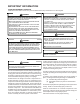
IMPORTANT INFORMATION SAFE REFRIGERANT HANDLING While these items will not cover every conceivable situation, they should serve as a useful guide. WARNING WARNING REFRIGERANTS ARE HEAVIER THAN AIR. THEY CAN "PUSH OUT" THE TO AVOID TO AVOID POSSIBLE EXPLOSION: • NEVER APPLY FLAME OR STEAM TO A REFRIGERANT CYLINDER. IF YOU OXYGEN IN YOUR LUNGS OR IN ANY ENCLOSED SPACE.
ComfortNet™ PRODUCT IDENTIFICATION A S X C 16 024 1 1 2 3 4,5 6 6 7 AA 8,9 Brand A - Amana® brand Engineering Major/Minor Revisions D - Deluxe Goodman® brand Type S Split System Voltage 1 - 208/230V Single-Phase 60 Hz 3 - 208/230V Three-Phase 60 Hz Type 4 - 460V Three-Phase 60 Hz C: Condenser R-22 H: Heat Pump R-22 X: Condenser R-410A 024 - 2 Tons Z: Heat Pump R-R410A 036 - 3 Tons Nominal Capacity 048 - 4 Tons Communication Feature C: 4-Wire Communication Ready SEER 16 - 16 SEE
PRODUCT IDENTIFICATION C A P F 1 2 3 4 1824 5,6,7,8 ComfortNet™ A 6 AA 9 10 11,12 Brand C Engineering* Major/Minor Revisions Indoor Coil Refrigerant Charge Unit Application A Upflow/Downflow Coil 2 = R-22 H Horizontal A-Coil 6 = R-410A or R-22 S Horizontal Slab Coil T Coated Coils 4 = R-410A Nominal Width for Gas Furnace A = Fits 14" Furnace Cabinet B = Fits 17-1/2" Furnace Cabinet C = Fits 21" Furnace Cabinet D = Fits 24-1/2" Furnace Cabinet N = Does Not Apply (Horizontal Slab Coils
ComfortNet™ PRODUCT IDENTIFICATION MB V C 1,2 3 4 Brand MB - Modular Blower 12 00 A A 1 4 5,6 7 8 9 Electrical 1: 208-230V/60Hz/1 PH Design Series Type V: A: First Series Speed Circuit Breaker Communication Feature A: No Circuit Breaker C: B: Circuit Breaker 4-Wire Communication Ready Airflow 12: 1200 CFM 16: 1600 CFM 20: 2000 CFM 6 Factory Heat 00 No Heat
PRODUCT IDENTIFICATION ComfortNet™ A V P T C 1830 1 2 3 4 5 6,7,8,9 1 11 6 AA 12 13,14 Brand A Airhandler Unit Application V Variable Speed Motor Engineering* Major/Minor Revisions Refrigerant Charge No Digit = R-22 Only 6 = R-410A or R-22 Cabinet Finish U: Unpainted P: Painted Electrical 1 208/240V, 1 Phase, 60 Hz N: Uncased Nominal Capacity Expansion Device Multi-Position & Downflow Applications F: Flowrator 1830 = 1-1/2 to 2-1/2 Tons T: Expansion Valve 3137 = 3 Tons Communications
ComfortNet™ PRODUCT IDENTIFICATION A V P T C 18 B 1 1 2 3 4 5 6,7 8 9 4 AA 10 11,12 Brand A Engineering* Single Piece Major/Minor Revisions Airhandler *Not used for inventory management Unit Application Refrigerant Charge C Ceiling Mount PSC Motor R Multi Position PSC Motor S Multi Position EEM Motor W Wall Mount PSC/EEM Motor V Multi Position Variable Speed Motor - 4 = R-410a Electrical 1 208/240V, 1 Phase, 60 Hz Cabinet Width Communicating B = 17-1/2" C = 21" D = 24-1/2" Cab
PRODUCT IDENTIFICATION ASXC16 AMANA® BRAND SPLIT X-COMMUNICATING CONDENSERS R-410A 16 SEER Model/Rev Description ASXC160**1AA Introduces Amana® brand 2-stage 16 SEER condensing units with R-410A, communicating models. ASXC160601BA Use ZPS49 compressor. ASXC160481BA SmartCoil® coils ASXC160(24/36)1BB Wiring diagram updated with notes. ASXC160(48-60)1BB Motor changed to Nidec. ASXC160(24/36)1BC ASXC160(48-60)1BC Introduces Ultratech® 2.0 compressor changes.
PRODUCT IDENTIFICATION DSXC16 DELUXE SPLIT X-COMMUNICATING CONDENSERS R-410A 16 SEER Model/Rev Description DSXC160**1AA Initial release of Goodman® Deluxe brand 2-stage 16 SEER condensing units with R410A, communicating models. DSXC160(24/36)1AB Wiring diagram updated with notes. DSXC160(24/36)1AC DSXC160(48-60)1BC Ultratech® 2.0 compressor. DSXC160481BA SmartCoil® coils. DSXC160601BA ZPS49K compressor. DSXC160(48-60)1BB Motor changed to Nidec.
PRODUCT IDENTIFICATION DSXC16 DELUXE SPLIT X-COMMUNICATING CONDENSERS R-410A 16 SEER Model/Rev Description DSXC160**1AA Initial release of Goodman® Deluxe brand 2-stage 16 SEER condensing units with R410A, communicating models. DSXC160(24/36)1AB Wiring diagram updated with notes. DSXC160(24/36)1AC DSXC160(48-60)1BC Ultratech® 2.0 compressor. DSXC160481BA SmartCoil® coils. DSXC160601BA ZPS49K compressor. DSXC160(48-60)1BB Motor changed to Nidec.
PRODUCT IDENTIFICATION DSZC16 DELUXE SPLIT Z-COMMUNICATING HEAT PUMP R-410A 16 SEER Model/Rev Description DSZC16**1AA Initial release of Goodman® brand Deluxe 2-stage 16 SEER heat pump units with R410A, communicating models. DSZC160(24/36)1AB DSZC160(48/60)1AB Sanhua (RANCO) reversing valves. DSZC160(24-48)1AC DSZC160601BA Release of models with accumulators and crankcase heaters. DSZC160(24-48)]1AD DSZC160601BB DSZC160481AE DSZC160601BC Ultratech® 2.0 compressor change.
PRODUCT IDENTIFICATION AVPTC****14 SINGLE PIECE AIR HANDLER MULTIPLE-POSITION VARIABLE SPEED PAINTED TXV WITH 4-WIRE COMMUNICATING CONTROL Model/Rev Description AVPTC183014AA AVPTC313714AA AVPTC426014AA Initial release of 13 SEER air handler with communicating control and serial communicating indoor blower motor. AVPTC183014AB AVPTC313714AB AVPTC426014AB Replaced PCBJA10 communicating air handler control board with PCBJA103.
PRODUCT IDENTIFICATION MBVC MODULAR BLOWER AIR HANDLER V-MULTI-POSITION VARIABLE-SPEED COMMUNICATING READY W/4-WIRES Model/Rev MBVC1200AA1-AA MBVC1600AA1-AA MBVC2000AA1-AA MBVC1200AA1-AB MBVC1600AA1-AB MBVC2000AA1-AB MBVC1200AA1-AC MBVC1600AA1-AC MBVC2000AA1-AC MBVC1200AA1-AD MBVC1600AA1-AD MBVC2000AA1-AD MBVC[1200, 1600, 2000]AA1-AE Description Introduction of module blower with variable speed blower motor with the new communicating control & serial communicating indoor blower motor.
PRODUCT IDENTIFICATION CAUF C-INDOOR COIL A-UPFLOW/DOWNFLOW UNCASED FLOWRATOR Model/Rev Description CAUF*****6AA Initial release of CAUF Dayton Upflow/Downflow coils. CAUF*****6BA Burr Oak Louvered Fin released in place of the Wavy Fin. CAUF****6*DA Replaced existing copper coils and other associated parts with aluminum components. CAUF*****6DB Drain pan material changed. CAUF1824A6RDB CAUF1824B6RDB Manufacturing Location Change from Dayton to Houston. Designated by "R".
PRODUCT IDENTIFICATION CSCF C-INDOOR COIL S-HORIZONTAL SLAB COIL C-UNPAINTED FLOWRATOR Model/Rev Description CSCF*****6AA Initial release of 13 SEER CSCF horizontal slab coils. CSCF*****6BA Burr Oak Louvered Fin released in place of the Wavy Fin. Rows reduced by one where applicable. CSCF1824N6BB CSCF3036N6BB CSCF3642N6CB CSCF4860N6CB Drain pan material changed. CSCF1824N6CA CSCF3036N6CA CSCF3642N6CA CSCF4860N6CA Replaced copper coils and other associated parts with aluminum components.
ACCESSORIES ComfortNet™ ASXC/DSXC 16 ASXC/DSXC 18 ASXC16024 ASXC16036 ASXC16048 ASXC16060 ASXC18036 ASXC18048 ASXC18060 DSXC16024 DSXC16036 DSXC16048 DSXC16060 DSXC18036 DSXC18048 DSXC18060 Anchor Bracket Kit X X X X X X X TX2N4A TXV Kit X TX3N4 TXV Kit TX5N4 TXV Kit X X X X CSR-U-1 Hard-start Kit CSR-U-2 Hard-start Kit CSR-U-3 Hard-start Kit Model Description ABK-20 FSK01A 1 Freeze Protection Kit Liquid Line Solenoid LSK02 Valve B1141643 3 24V Transformer
ACCESSORIES EXPANSION VALVE KITS For Applications requiring 1/4 FLARE CONNECTION BULB TO BE LOCATED AT 10 OR 2 O'CLOCK a field installed access fitting BULB SUCTION LINE EVAPORATOR COIL PISTON SEAL SUPPLIED W/ KIT SEAL SUPPLIED W/ KIT EXPANSION VALVE TAILPIECE SEAL DISTRIBUTOR BODY REMOVE BEFORE INSTALLING EXPANSION VALVE 3/8"SWEAT 7/8" NUT For Applications not requiring 1/4' FLARE CONNECTION a field installed access fitting BULB TO BE LOCATED AT 10 OR 2 O'CLOCK BULB SUCTION LINE PISTON EXP
ACCESSORIES FSK01A FREEZE THERMOSTAT KIT Wire Nut Y Bl ac k Y k ac Bl Wire Nut Install Line Thermostat Here Install Line Thermostat Here Wire Nut Bla ck Bla ck Wire Nut Y Y 19
ACCESSORIES NO HEAT HKR-03* HKR05-(C)' HKR-06* HKR-08(C)* HKR-10(C)* HKA-15C* HKA-20C* ^HKR3-15* ^HKR3-20A ELECTRIC HEAT KIT MBVC1200AA-1** - X X X X X X - - - MBVC1600AA-1** - X X X X X X - - - MBVC2000AA-1** - X X X X X - X - - BLOWER X = Allowable combinations ^ = Circuit 1: Single Phase for Air Handler Motor Circuit 2: 3-Phase for HKR3 Heater Kits - = Restricted combinations HK* SERIES ELETRIC HEAT KITS ELECTRIC HEAT KIT APPLICATIONS - MBVC 20
ACCESSORIES ELECTRIC HEAT KIT APPLICATIONS - AVPTC MODELS HKR-03* HKR-05*/-05C* HKR-06* HKR-08*/-08C* 1 HKR-10*/-10C* HKR-15C* HKR-20C* HKR-21C* HKA-15C* HKA-20C* 1 --- AVPTC183014A* X X X X X --- --- --- --- AVPTC313714A* X X X X1 X1 X2 --- --- X2 X AVPTC426014A* X X X X X X X3 X3 X X3 * Revision level that may or may not be designated. C Circuit breaker option.
ACCESSORIES AVPTC**14** AVPTC Heat Kit Applications 36C14-A* 48C14-A* 42D14-A* †† ††† 24B14-A* 30C14-A* HKSX03XC X X HKSX05XC X X X X X X X HKSX06XC X X X X X X X HKSX08XC X X X X X X X HKSX10XC X X 48D14-A* 60D14-A* X X X X X X HKSX15XF* X X X X X HKSX20XF* X X X X X HKSC05XC X X X X X X X HKSC08XC X X X X X X X HKSC10XC X X X X X X X HKSC15XA X X X X X HKSC15XB X X X X X HKSC15XF* X X X X X X X X X X X
ACCESSORIES READY 15 AVPTC AVPTC Heat Kit Selection Type / Model 25B14* 29B14* 37B14* 31C14* 37C14* 59C14* 37D14* 59D14* 49D14* 61D14* HKSX03XC* X X X HKSX05XC* X X X X X X X X X X HKSX06XC* X HKSX08XC* X X X X X X X X X X X X X X X X X X HKSX10XC* X X X X X X X X X X X HKSC05XC* X X X X X X X X X X HKSC08XC* X X X X X X X X X X HKSC10XC* X X X X X X X X X X HKSC15XA* X X X X X X X X X X HKSC15XB* X X
PRODUCT DESIGN This section gives a basic description of cooling unit operation, its various components and their basic operation. Ensure your system is properly sized for heat gain and loss according to methods of the Air Conditioning Contractors Association (ACCA) or equivalent. The ZPS two-step modulated scroll uses a single step of unloading to go from full capacity to approximately 67% capacity.
PRODUCT DESIGN • Compliant scroll compressors perform "quiet" shutdowns that allow the compressor to restart immediately without the need for a time delay. This compressor will restart even if the system has not equalized. NOTE: Operating pressures and amp draws may differ from standard reciprocating compressors. This information can be found in the unit's Technical Information Manual.
PRODUCT DESIGN Communicating Unitary Control (UC) PCB The Communicating System Unitary Control PCB is a microprocessor-based control for heat pump and air conditioning condensing units with single-phase compressors up to 5 ton capacity operating on standard residential or Delta and Wye commercial power.
SYSTEM OPERATION COOLING The refrigerant used in the system is R-410A. It is a clear, colorless, non-toxic and non-irritating liquid. R-410A is a 50:50 blend of R-32 and R-125. The boiling point at atmospheric pressure is -62.9°F. A few of the important principles that make the refrigeration cycle possible are: heat always flows from a warmer to a cooler body. Under lower pressure, a refrigerant will absorb heat and vaporize at a low temperature.
SYSTEM OPERATION DEFROST CYCLE - COMFORTNETTM MODELS The defrosting of the outdoor coil is jointly controlled by the UC PCB and the outdoor coil temperature (OCT) sensor. The OCT sensor is clamped to a feeder tube entering the outdoor coil. Defrost timing periods of 30, 60, 90 or 120 minutes may be selected via the dipswitch settings on the UC PCB. In a communicating system, the defrost timing periods can also be selected in the communicating thermostat user menu.
SYSTEM OPERATION COOLING CYCLE Reversing Valve (Energized) Indoor Coil Outdoor Coil Accumulator Thermostatic Expansion Valve Bi-Flow Filter Dryer Check Valve HEATING CYCLE Reversing Valve (De-Energized) Outdoor Coil Indoor Coil Accumulator Thermostatic Expansion Valve Bi-Flow Filter Dryer Check Valve 29
SYSTEM OPERATION EXPANSION VALVE/CHECK VALVE ASSEMBLY IN COOLING OPERATION EXPANSION VALVE/CHECK VALVE ASSEMBLY IN HEATING OPERATION Most expansion valves used in current Goodman/Amana® Brand Heat Pump products use an internally checked expansion valve. This type of expansion valve does not require an external check valve as shown above. However, the principle of operation is the same.
TROUBLESHOOTING CHART COOLING/HP ANALYSIS CHART Pow er Failure Blow n Fus e Loose Connection Shorted or Broken Wires Open Fan Ov erload Faulty Thermos tat Faulty Trans f ormer Shorted or Open Capac itor Internal Compres sor Ov erload Open Shorted or Grounded Compress or Compres s or Stuck Faulty Compres s or Contac tor Faulty Fan Relay Open Control Circuit Low V oltage Faulty Ev ap.
SERVICING TABLE OF CONTENTS S-1 S-2 S-3E S-4 CHECKING VOLTAGE ................................................ 33 CHECKING WIRING ................................................... 33 CTK0*** COMFORTNETTM THERMOSTAT .............. 33 CHECKING TRANSFORMER AND CONTROL CIRCUIT ...................................... 46 S-6 CHECKING TIME DELAY RELAY ............................... 46 S-8A CHECKING UNITARY (UC) CONTROL COMPRESSOR CONTACTOR/RELAY CONTACTS .........................................................
SERVICING S-1 CHECKING VOLTAGE 1. Remove outer case, control panel cover, etc., from unit being tested. With power ON: NOTE: When operating electric heaters on voltages other than 240 volts, refer to the System Operation section on electric heaters to calculate temperature rise and air flow. Low voltage may cause insufficient heating. S-2 CHECKING WIRING WARNING Line Voltage now present. 2.
SERVICING between the thermostat and subsystems (indoor/outdoor unit) and between subsystems is the key to unlocking the benefits and features of the ComfortNet system. Two-way digital communications is accomplished using only two wires. The thermostat and subsystem controls are powered with 24 VAC Thus, a maximum of 4 wires between the equipment and thermostat is all that is required to operate the system.
SERVICING 1 C 2 R CTK0* Thermostat 1 C 2 R 1 40VA Transformer (included in CTK0*** kit) 208/230 VAC 1 2 2 R C R C CT Compatible Modular Blower Integrated Control Module CT Compatible AC/HP Integrated Control Module 40VA Transformer (included in CTK0*** kit) 24 VAC 208/230 VAC System Wiring Using Three-Wires between Air Handler and AC / HP and Four Wires between Air Handler and Thermostat RECOMMENDED CTK 03/04 WIRING SCHEME: Three wires should be utilized between the indoor and outdoor units
SERVICING Diagnostics Accessing the air handler’s diagnostics menu provides ready access to the last six faults detected by the air handler. Faults are stored most recent to least recent. Any consecutively repeated fault is stored a maximum of three times. Example: A clogged return air filter causes the air handler’s motor to repeatedly enter a limiting condition. The control will only store this fault the first three consecutive times the fault occurs.
SERVICING 7 SEGMENT LED (characters will alternate) (no display) On Ec E5 EF d0 d1 d4 b0 b1 b2 b3 b4 b5 b6 b7 b9 C1 C2 P1 P2 h1 h2 FC FH F H1 H2 dF DES CRIPTION OF CONDITION INTERNAL CONTROL FAULT / NO POWER STANDBY, WAITING FOR INPUTS HEATER KIT TOO LARGE, TOO SMALL, OR NO MATCH FUSE OPEN AUXILIARY SWITCH OPEN DATA NOT ON NETWORK INVALID DATA ON NETWORK INVALID MEMORY CARD DATA BLOWER MOTOR NOT RUNNING BLOWER MOTOR COMMUNICATION ERROR BLOWER MOTOR HP MISMATCH BLOWER MOTOR OPERATING IN POWER, TEMP.
x 5 Flashes x No air handler operation. x Integrated control module LED display provides the indicated error code. x ComfortNet thermostat displays “Battery Power” x Air handler fails to operate x Integrated control module LED display provides no signal.
x Operation different than expected or no operation. x Integrated control module LED display provides indicated error code. x ComfortNet thermostat “Call for Service” icon illuminated. x ComfortNet thermostat scrolls “Check Air Handler” message. Symptoms of Abnormal Operation (Communicating & Non-communicating Thermostat) x Air handler fails to operate. x Integrated control module LED display provides indicated error code. x ComfortNet thermostat “Call for Service” icon illuminated.
x Integrated control module has lost communications with circulator blower motor. x Circulator blower motor horse power in shared data set does not match circulator blower motor horse power. x Circulator blower motor is operating in a power, temperature, or speed limiting condition. x Circulator blower motor senses a loss rotor control. x Circulator blower motor senses high current. 6 Flashes 6 Flashes 6 Flashes 6 Flashes x Air handler fails to operate.
Symptoms of Abnormal Operation (Communicating & Non-communicating Thermostat) x Air handler fails to operate. x Integrated control module LED display provides indicated error code. x ComfortNet™ thermostat “Call for Service” icon illuminated. x ComfortNet thermostat scrolls “Check Air Handler” message. x Air handler fails to operate. x Integrated control module LED display provides indicated error code. x ComfortNet thermostat “Call for Service” icon illuminated.
x Heater kit selected via dipswitches is too small for heater kits specified in shared data set x Heater kit selected via dipswitches does not heater kits specified in shared data set x EC EC EF x Electric heat airflow is higher than expected on a call for W1 or Auxiliary/Emergency heat x Integrated control module LED display provides the indicated error code.
x Data not yet on network. x Invalid data on network. x Invalid memory card data. d1 d4 x Air handler blower fails to operate. x Integrated control module LED display provides indicated error code. x ComfortNet™ thermostat “Call for Service” icon illuminated. x ComfortNet™ thermostat scrolls “Check Air Handler” message. x Operation different than expected or no operation. x Integrated control module LED display provides indicated error code.
x Circulator blower motor horse power in shared data set does not match circulator blower motor horse power. x Circulator blower motor is operating in a power, temperature, or speed limiting condition. x Circulator blower motor senses a loss rotor control. x Circulator blower motor senses high current. b2 b3 b4 x Air handler blower fails to operate. x Integrated control module LED display provides indicated error code. x ComfortNet™ thermostat “Call for Service” icon illuminated.
x Circulator blower motor shuts down for over or under voltage condition. x Circulator blower motor shuts down due to over temperature condition on power module. x Circulator blower motor does not have enough information to operate properly. Motor fails to start 40 consecutive times. x Airflow is lower than demanded. b7 b9 x Air handler blower fails to operate. x Integrated control module LED display provides indicated error code. x ComfortNet™ thermostat “Call for Service” icon illuminated.
SERVICING S-4 CHECKING TRANSFORMER AND CONTROL CIRCUIT 3. Using an ohmmeter, check for continuity across terminals 3 and 1, and 4 and 5. 4. Apply 24 volts to terminals H1 and H2. Check for continuity across other terminals - should test continuous. If not as above - replace. HIGH VOLTAGE! Disconnect ALL power before servicing or installing. Multiple power sources may be present. Failure to do so may cause property damage, personal injury or death.
SERVICING S-9 CHECKING HIGH AND LOW VOLTAGE TO ECM MOTOR HIGH VOLTAGE! Disconnect ALL power before servicing or installing. Multiple power sources may be present. Failure to do so may cause property damage, personal injury or death. 1. Measure voltage between black and brown motor leads. This should measure 208/230 volts depending on your power supply. 2. If voltage is present proceed to check fan relay contacts and voltage.
ON ON • Compressor and outdoor fan are off. • Low pressure switch trip 3 times within same thermostat demand. • Thermostat demand is present. • Integrated control module diagnostic/status LED’s display the indicated code. • ComfortNet™ thermostat “Call for Service” icon illuminated. • ComfortNet™ thermostat scrolls “Check Air Conditioner” or “Check Heat Pump” message. Green OFF • Compressor and outdoor fan are off. • Thermostat demand is present.
2 Flashes 3 Flashes ON OFF • Compressor and outdoor fan are off. • Low pressure switch trip 3 times within same thermostat demand. • Thermostat dema nd is present. • Integrated control module diagnostic/status LED’s display the indicated code. • ComfortNet™ thermostat “Call for Service” icon illuminated. • ComfortNet™ thermostat scrolls “Check Air Conditioner” or “Check Heat Pump” message. • Run time for last 4 cycles is less than 3 minutes each. • Compressor protector has not tripped.
• Compressor and outdoor fan are off. • Compressor protector trips four consecutive times. • Avera ge run time between trips is less than 15 seconds. • Integrated control module diagnostic/status LED’s display the indicated code. • ComfortNet™ thermostat “Call for Service” icon illuminated. • ComfortNet™ thermostat scrolls “Check Air Conditioner” or “Check Heat Pump” message. • Compressor and outdoor fan are off for greater than 4 hours. • Low pressure and high pressure switc hes are closed.
• Air conditioner/heat pump may appear to be operating normally. • Compressor protector may be open (compressor and outdoor fan off). • Integrated control module diagnostic/status LED’s display the indicated code. • Compressor and outdoor fan are off. • Low pressure and high pressure switches are closed. • Integrated control module diagnostic/status LED’s display the indicated code. • ComfortNet™ thermostat “Call for Service” icon illuminated.
• Compressor is off. • Integrated control module diagnostic/status LED’s display the indicated code. • Air conditioner/heat pump may appear tobe operating normally. • Integrated control module diagnostic/status LED’s display the indicated code.
SERVICING PCBHR104 7 SEGMENT LED (DS2) 0 0 0 0 0 0 0 0 0 0 0 0 8 A A b b C C C d d d d d d d d E E F H L L L L L P P P P P 7 SEGMENT LED (DS1) n 1 1 2 2 3 4 5 6 7 8 9 8 2 3 0 9 3 1 2 F t E 0 1 2 3 4 E 5 t 8 1 2 6 7 8 3 1 2 0 d DESCRIPTION OF CONDITION Standby Low Pressure CO Trip Low Side Fault High Pressure CO Trip High Side Fault Short Cy cling Locked Rotor Open Circuit Open Start Circuit Open Run Circuit No Line Voltage Low Pilot Voltage Pow er Up Outdoor Air Temp Sensor Fault Outdoor Coil Temp Senso
PCBHR104 SERVICING 3934%- 42/5",%3(//4).' 5.)4!29 $)!'./34)# #/$%3 3YMPTOMS OF !BNORMAL /PERATION ,EGACY #OMFORT.ET 4HERMOSTAT $IAGNOSTIC 3TATUS ,%$ $ISPLAY #ODES $IGIT $IGIT $IGIT s Integrated control module diagnostic/status LED display shows the indicated code. s #OMFORT.ET THERMOSTAT displays ‘---‘ in the temperature display area. ",!.+ A 2 s Heat pump fails to operate in heating mode. s Integrated control module diagnostic/status LED display shows the indicated code. s #OMFORT.
SERVICING PCBHR104 5.)4!29 $)!'./34)# #/$%3 3YMPTOMS OF !BNORMAL /PERATION ,EGACY #OMFORT.ET 4HERMOSTAT $IAGNOSTIC 3TATUS ,%$ $ISPLAY #ODES $IGIT $IGIT $IGIT s Air conditioner/heat pump fails to operate. s Integrated control module diagnostic/status LED display shows the indicated code. s #OMFORT.ET THERMOSTAT displays error message. ",!.+ d 0 s Air conditioner/heat pump fails to operate. s Integrated control module diagnostic/status LED display shows the indicated code. s #OMFORT.
SERVICING PCBHR104 5.)4!29 $)!'./34)# #/$%3 3YMPTOMS OF !BNORMAL /PERATION ,EGACY #OMFORT.ET 4HERMOSTAT $IAGNOSTIC 3TATUS ,%$ $ISPLAY #ODES $IGIT $IGIT s Air conditioner/heat pump ",!.+ fails to operate. s Integrated control module diagnostic/status LED display shows the indicated code. s #OMFORT.ET THERMOSTAT displays error message. d 3 s Air conditioner/heat pump fails to operate. s Integrated control module diagnostic/status LED display shows the indicated code. s #OMFORT.
SERVICING PCBHR104 Digit 3 Digit 2 Digit 1 L 1 Low Pressure Cut Out Lockout (3 Trips) Four consecutive compressor protector trips with average run time between trips greater than 1 minute and less than 15 minutes. Low pressure and high pressure switches are closed. Integrated control module diagnostic/status LED display shows the indicated code. 0 2 High Side Fault Compressor and outdoor f . Thermostat demand is present.
SERVICING PCBHR104 Digit 3 Digit 2 Digit 1 Run time for last 4 cycles is less than 3 minutes each. Compressor protector has not tripped. Low pressure and high pressure switches are closed. Integrated control module diagnostic/status LED display shows the indicated code. 0 3 Short Cycling Compressor and outdoor f . Compressor protector trips four consecutive times. Average run time between trips is less than 15 seconds.
SERVICING PCBHR104 Digit 3 Compressor and outdoor . f Low pressure and high pressure switches are closed. Open start circuit has been detected 4 times with 5 minute delay between each detection. Integrated control module diagnostic/status LED display shows the indicated code. Digit 2 Digit 1 L 6 Open Start Circuit Lockout 06 Compressor start winding is open. Failed compressor run capacitor. Faulty run capacitor wiring. Compressor not properly wired to control. Faulty compressor wiring.
PCBHR104 SERVICING Digit 2 Digit 1 Air conditioner/heat pump may appear to be operating normally. Compressor protector may be open (compressor and outdoor f Integrated control module diagnostic/status LED display shows the indicated code. H 8 Air conditioner/heat pump may appear to be operating normally. Integrated control module diagnostic/status LED display shows the indicated code. 0 . Integrated control module diagnostic/status LED display shows the indicated code.
SERVICING S-12 CHECKING HIGH PRESSURE CONTROL mately 50 PSIG for heat pumps and 95 PSIG for air conditioners. Test for continuity using a VOM and if not as above, replace the control. HIGH VOLTAGE! Disconnect ALL power before servicing or installing. Multiple power sources may be present. Failure to do so may cause property damage, personal injury or death. The high pressure control capillary senses the pressure in the compressor discharge line.
SERVICING 4. If the reading is near to the actual value of the capacitor (i.e. the printed value on the capacitor). The capacitor is good. (Note that the reading may be less than the actual printed value of the capacitor). 5. If you read a significantly lower capacitance or none at all, then capacitor is dead and must be replaced. S-16G CHECKING EMERSON ULTRATECHTM ECM MOTORS DESCRIPTION The AVPTC and MBVC models utilize an Emerson, 4-wire variable speed ECM blower motor.
SERVICING 8. Check motor mounting bracket. Ensure mouting bracket is tightly secured to the housing. Ensure bracket is not cracked or broken. TM Emerson UltraCheck-EZ Diagnostic Tool The Emerson UltraCheck-EZTM diaganostic tool may be used to diagnose the ECM motor. HIGH VOLTAGE! Disconnect ALL power before servicing or installing. Multiple power sources may be present. Failure to do so may cause property damage, personal injury or death.
SERVICING 3. Remove the blower assembly from the air handler or modular blower. 1 2 } Lines 1 and 2 will be connected for 12OVAC Power Connector applications only 3 Gnd 4 AC Line Connection 5 AC Line Connection 4. Remove the (3) screws securing the control/end bell to the motor. Separate the control/end bell. Disconnect the 3-circuit harness from the control/end bell to remove the control/end bell from the motor. 5. Inspect the NTC thermistor inside the control/end bell (see figure below).
SERVICING Motor Checks HIGH VOLTAGE! Disconnect ALL power before servicing or installing. Multiple power sources may be present. Failure to do so may cause property damage, personal injury or death. 1. Disconnect power to air handler or modular blower. Tap C Tap D* OFF ON OFF ON 1 1 1 2 2 2 2 Cooling Airflow Speed Tap (* indicates factory setting) Airflow Adjust Dipswitches - Used to adjust the airflow +/10% 2. Disassemble motor as described in steps 2 through 4 above. 4.
SERVICING 20 kW 21 kW* OFF ON 15 kW OFF ON 10 kW OFF ON OFF ON 9 9 9 9 10 10 10 10 11 11 11 11 Electric Heating Airflow (* indicates factory setting) 8 kW 6 kW 5 kW 3 kW OFF ON OFF ON OFF ON OFF ON 9 9 9 9 10 10 10 10 11 11 11 11 Electric Heating Airflow (* indicates factory setting) The table on the following page indicates the airflow that corresponds to the available dipswitch settings.
SERVICING MBVC Airflow Table Speed Selection Dip Switches Cool Selection Switches Adjust Selection Switches TAP 1 A OFF OFF OFF OFF OFF OFF B ON OFF C D Profiles 2 3 4 Profile Selection Switches 5 9 10 11 MBVC1200* MBVC16000* MBVC2000* 3 ON ON ON 600 800 800 5 ON ON OFF 600 800 800 6 ON OFF ON 635 800 800 8 ON OFF OFF 740 1000 1000 10 OFF ON ON 1000 1000 1200 15 OFF ON OFF 1400 1500 1500 20 OFF OFF ON NR NR 2000 Low Stage Cool High Sta
BLOWER PERFORMANCE DATA HTR kW MBVC1200* MBVC1600* MBVC2000* SWITCH 9 SWITCH 10 SWITCH 11 3 600 800 800 ON ON ON 5 600 800 800 ON ON OFF 6 635 800 800 ON OFF ON 8 740 1000 1000 ON OFF OFF 10 1000 1000 1200 OFF ON ON 15 1400 1500 1500 OFF ON OFF 20 NR NR 2000 OFF OFF ON 21 NR NR NR ON^ ON^ ON^ ^ Factory setting MODEL LOW STAGE COOL HIGH STAGE COOL 400 600 MBVC1200 MBVC1600 MBVC2000 ADJUST SELECTION SWITCHES COOL SELECTION SWITCHES PROF
SERVICING AVPTC Airflow Table Cooling/Heat Pump Airflow Table Model S p ee d S ele ction D ip S witch es C oo l S ele ction S witch es Ad ju st S elec tio n S w it che s 1 O FF 2 O FF T R IM 0% 3 O FF 4 OF F B C ON O FF O FF ON ON O FF OF F ON D ON ON + 1 0% - 10 % 0% ON ON AVPTC313714* TO SET A IRF L OW : 1.Select appropriate m odel from C ool ing/H eat P um p Airfl ow T able. Bas ed on des ired Airflow f or y our ap plication select c orres ponding tap (A ,B,C or D).
SERVICING Speed Selection Dip Switches Cool Selection Switches TAP S1 Adjust Selection Switches S2 S3 Profile Selection Switches S4 S5 S6 Cooling/Heat Pump Airflow Table Continuous Fan Speed S12 S13 OFF OFF OFF OFF OFF OFF OFF ON OFF ON OFF ON OFF ON OFF OFF ON ON OFF ON OFF ON A OFF B C D ON OFF ON ON Profiles Pre-Run A ------- ON ON ON Short-Run -------- ON Model AVPTC24B14** AVPTC30C14** ON OFF Delay 60 sec/100% AVPTC36C14** B ------- 30 sec/50% C ---
SERVICING READY 15 AVPTC AIRFLOW TABLES Cooling/Heat Pump Airflow Table Tap Low Stage High Stage MODEL Speed Selection Dip Switches Cool Selection Switches TAP A S1 OFF Adjust Selection Switches S2 S3 Profile Selection Switches S4 S5 Continuous Fan Speed S6 OFF OFF OFF OFF OFF AVPTC25B14 1085 OFF 375 610 B 545 795 C 630 930 D 740 1085 A 590 880 B 705 1055 C 845 1265 D 910 1360 A 610 875 B 810 1225 ON OFF C OFF ON ON OFF ON OFF ON Profiles Pre-Run A ON
SERVICING ELECTRIC HEAT AIRFLOW TABLE Htr kW 9 10 11 AVPTC24B14A* ON 3 ON ON 5 ON ON OFF AVPTC30C14A* AVPTC36C14A* AVPTC48C14* AVPTC42D14A* + AVPTC48D14A*++ AVPTC60D14A*+++ 550 600 NR NR 850** NR NR 650 700 850 850 1250 1250 1250 6 ON OFF ON 700 750 900 900 1300 1300 1300 8 ON OFF OFF 800 875 1000 1000 1500 1500 1500 10 OFF ON 850 950 1200 1200 1550 1550 1550 15 OFF ON OFF NR NR 1440 1440 1720 1720 1780 NR NR 1500 1500 NR NR NR NR NR 1
SERVICING S-17 CHECKING COMPRESSOR WARNING Hermetic compressor electrical terminal venting can be dangerous. When insulating material which supports a hermetic compressor or electrical terminal suddenly disintegrates due to physical abuse or as a result of an electrical short between the terminal and the compressor housing, the terminal may be expelled, venting the vapor and liquid contents of the compressor housing and system.
SERVICING 1. DO NOT remove protective terminal cover. Disconnect the three leads going to the compressor terminals at the nearest point to the compressor. 2. Identify the leads and using an ohmmeter on the R x 10,000 scale or the highest resistance scale on your ohmmeter check the resistance between each of the three leads separately to ground (such as an unpainted tube on the compressor). 3.
SERVICING 1. Remove unit wiring from disconnect switch and wire a test cord to the disconnect switch. S-21 CHECKING REVERSING VALVE AND SOLENOID NOTE: The wire size of the test cord must equal the line wire size and the fuse must be of the proper size and type. Occasionally the reversing valve may stick in the heating or cooling position or in the mid-position. 2.
SERVICING S-26 TESTING TEMPERATURE SENSORS (COMFORTNET READY MODELS ONLY) The ASXC and DSXC ComfortNet ready air conditioner models are factory equipped with an outdoor air temperature (OAT) sensor. The OAT sensor allows the outdoor air temperature to be displayed on the CTK0* thermostat when used with the ASXC and DSXC models. The ASZC and DSZC ComfortNet ready heat pump models are equipped with both an outdoor air temperature (OAT) sensor and an outdoor coil temperature (OCT) sensor.
SERVICING 1. Turn on power to air handler or modular blower. WARNING • Low voltage wires that are shorted, grounded or broken. • Communicating wires that are not connected to the proper terminals at the connector. • 24 volt common outside and inside are not at the same ground potential • Bias dip switch setting conflicts between indoor board and outdoor board.
SERVICING components. This leads to a somewhat non-traditional manner in which the system components receive commands for system operation. All system commands are routed from the component through the network to the appropriate destination component. NOTE: The individual subsystems will cease operation if the request for operation is NOT refreshed after 5 minutes. This is a built-in safe guard to prevent the possibility of runaway operation. 1.0 Cooling Operation - Low and High Stage Cool 1.
SERVICING handler control along with a fan demand. The control energizes the variavble speed ECM motor at fan demand provided by the thermostat. The fan demand provided by the thermostat will be 30%, 50%,or 70% of the air handler's maximum airflow capability. The continuous fan demand is set from the thermostat as low, medium, or high. 3.2 If the thermostat demand for continuous fan is removed, the CTK0* thermostat commands the integrated air handler control to end continuous fan operation.
SERVICING The air handler control determines which airflow demand is greatest and applies that demand when operating the ECM blower motor. 2.11 The system operates at high stage heat pump heating plus auxiliary heat. 2.12 Once the thermostat demand is satisfied, the CTK0* thermostat commands the heat pump to end heat pump heating operation. The compressor and outdoor fan motor are de-energized. The air handler/modular blower is commanded to end auxiliary heat operation.
SERVICING S-60 ELECTRIC HEATER (OPTIONAL ITEM) Optional electric heaters may be added, in the quantities shown in the specifications section, to provide electric resistance heating. Under no condition shall more heaters than the quantity shown be installed. The low voltage circuit in the air handler is factory wired and terminates at the location provided for the electric heater(s). A minimum of field wiring is required to complete the installation.
SERVICING S-61A CHECKING HEATER LIMIT CONTROL(S) Each individual heater element is protected with a limit control device connected in series with each element to prevent overheating of components in case of low airflow. This limit control will open its circuit at approximately 150°F. S-100 REFRIGERATION REPAIR PRACTICE DANGER Always remove the refrigerant charge in a proper manner before applying heat to the system.
SERVICING S-101 LEAK TESTING (NITROGEN OR NITROGEN-TRACED) WARNING To avoid the risk of fire or explosion, never use oxygen, high pressure air or flammable gases for leak testing of a refrigeration system. WARNING To avoid possible explosion, the line from the nitrogen cylinder must include a pressure regulator and a pressure relief valve. The pressure relief valve must be set to open at no more than 150 psig. Pressure test the system using dry nitrogen and soapy water to locate leaks.
SERVICING S-103 CHARGING WARNING REFRIGERANT UNDER PRESSURE! * Do not overcharge system with refrigerant. * Do not operate unit in a vacuum or at negative pressure. Failure to follow proper procedures may cause property damage, personal injury or death. CAUTION Use refrigerant certified to AHRI standards. Used refrigerant may cause compressor damage and is not covered under the warranty. Most portable machines cannot clean used refrigerant to meet AHRI standards.
SERVICING NOTE: Do NOT adjust the charge based on suction pressure unless there is a gross undercharge. 4. Disconnect manifold set, installation is complete. SUBCOOLING FORMULA = SATURATED LIQUID TEMP. - LIQUID LINE TEMP. NOTE: Check the Schrader ports for leaks and tighten valve cores if necessary. Install caps fingertight.
SERVICING 1. Attach an accurate thermometer or preferably a thermocouple type temperature tester to the liquid line as it leaves the condensing unit. 2. Install a high side pressure gauge on the high side (liquid) service valve at the front of the unit. 3. Record the gauge pressure and the temperature of the line. 4. Review the technical information manual or specification sheet for the model being serviced to obtain the design subcooling. 5.
SERVICING Pressure vs. Temperature Chart R-410A PSIG 12 14 16 18 20 22 24 26 28 30 32 34 36 38 40 42 44 46 48 50 52 54 56 58 60 62 64 66 68 70 72 74 76 78 80 82 84 86 88 90 92 94 96 98 100 102 104 106 108 110 112 °F -37.7 -34.7 -32.0 -29.4 -36.9 -24.5 -22.2 -20.0 -17.9 -15.8 -13.8 -11.9 -10.1 -8.3 -6.5 -4.5 -3.2 -1.6 0.0 1.5 3.0 4.5 5.9 7.3 8.6 10.0 11.3 12.6 13.8 15.1 16.3 17.5 18.7 19.8 21.0 22.1 23.2 24.3 25.4 26.4 27.4 28.5 29.5 30.5 31.2 32.2 33.2 34.1 35.1 35.5 36.9 PSIG 114.0 116.0 118.0 120.0 122.
SERVICING REQUIRED LIQUID LINE TEMPERATURE LIQUID PRESSURE AT SERVICE VALVE (PSIG) 189 195 202 208 215 222 229 236 243 251 259 266 274 283 291 299 308 317 326 335 345 354 364 374 384 395 406 416 427 439 450 462 474 486 499 511 88 8 58 60 62 64 66 68 70 72 74 76 78 80 82 84 86 88 90 92 94 96 98 100 102 104 106 108 110 112 114 116 118 120 122 124 126 128 REQUIRED SUBCOOLING TEMPERATURE (°F) 10 12 14 16 56 54 52 50 58 56 54 52 60 58 56 54 62 60 58 56 64 62 60 58 66 64 62 60 68 66 64 62 70 68 66 64 72 70 68
SERVICING CHECKING COMPRESSOR EFFICIENCY The reason for compressor inefficiency is broken or damaged scroll flanks on Scroll compressors, reducing the ability of the compressor to pump refrigerant vapor. The condition of the scroll flanks is checked in the following manner. 1. Attach gauges to the high and low side of the system. 2. Start the system and run a “Cooling Performance Test. If the test shows: Install a field supplied suction line drier.
SERVICING ALUMINUM INDOOR COIL CLEANING (Qualified Servicer Only) To determine proper airflow, proceed as follows: This unit is equipped with an aluminum tube evaporator coil. The safest way to clean the evaporator coil is to simply flush the coil with water. This cleaning practice remains as the recommended cleaning method for both copper tube and aluminum tube residential cooling coils.
ACCESSORIES WIRING DIAGRAMS HIGH VOLTAGE! DISCONNECT ALL POWER BEFORE SERVICING OR INSTALLING THIS UNIT. MULTIPLE POWER SOURCES MAY BE PRESENT. FAILURE TO DO SO MAY CAUSE PROPERTY DAMAGE, PERSONAL INJURY OR DEATH. 3-Phase Heat Kit 25kW Heat Kit Wiring is subject to change. Always refer to the wiring diagram on the unit for the most up-to-date wiring.
OAS DT R S YL CS CONTROLS SHOWN WITH THERMOSTAT IN 'OFF' POSITION.
DT C R OAS YL CS AUX S C Y2 COMP MAIN BK RD NOTE 4 BK CONTROLS SHOWN WITH THERMOSTAT IN 'OFF' POS ITION.
YL R S C Y2 CS RD SEE NOTE 3 DT C AUX COMP MAIN BR PU BK RD (LOW) LPS NOTES: 1. USECOPPER SUPPLY WIRESONLY. 2. USE 40VA T RANSFORMER MINIMUM FOR SYSTEM 3. IF DT ISNOTPRESENT,HPS BL/PK WIREGOESDIRECTLY TO TERMI NAL E29. 4. CONTROLSSHOWN WITHTHERMOSTATIN "OFF"POSITION. 5. COMMON SIDE OF 24VAC CONTROL CIRCUITMUST BE GROUNDED. 6. USE N.E.C.CLASS 2 WIRES.
C R RD SEE NOTE 3 DT YL CS Y2 S C AUX GR/YL BK BR WH YL BL MAIN COMP BK BL/PK LPS RVS 6. USE N.E.C. CLASS 2 WIRES. NOTES: 1. USE COPPER SUPPLY WIRESONLY. 2. USE 40VA T RANSFORMER MINIMUM FOR SYSTEM 3. IF DT IS NOTPRESENT, HPS BL/PK WIRE GOES DIRECTLY TOTERMINAL E29. 4. CONTROLSSHOWN WITHTHERMOSTAT IN "OFF" POSITION. 5. COMMON SIDE OF 24VACCONTROLCIRCUIT MUST BE GROUNDED.
ACCESSORIES WIRING DIAGRAMS HIGH VOLTAGE! DISCONNECT ALL POWER BEFORE SERVICING OR INSTALLING THIS UNIT. MULTIPLE POWER SOURCES MAY BE PRESENT. FAILURE TO DO SO MAY CAUSE PROPERTY DAMAGE, PERSONAL INJURY OR DEATH.
ACCESSORIES WIRING DIAGRAMS HIGH VOLTAGE! DISCONNECT ALL POWER BEFORE SERVICING OR INSTALLING THIS UNIT. MULTIPLE POWER SOURCES MAY BE PRESENT. FAILURE TO DO SO MAY CAUSE PROPERTY DAMAGE, PERSONAL INJURY OR DEATH.
ACCESSORIES WIRING DIAGRAMS HIGH VOLTAGE! DISCONNECT ALL POWER BEFORE SERVICING OR INSTALLING THIS UNIT. MULTIPLE POWER SOURCES MAY BE PRESENT. FAILURE TO DO SO MAY CAUSE PROPERTY DAMAGE, PERSONAL INJURY OR DEATH.