
Install Instructions


10
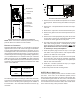
FEMALE CONNECTIONS
SIDE VIEW
W
A
RNING
SOFTW
A
RE VER.
TOP
FRONT VIEW
AVPTC Motor Orientation
C
ONDENSATE
R
EMOVAL
The coil drain pan has a primary and an optional secondary
drain with 3/4" NPT female connections. The connectors re-
quired can be 3/4" NPT male either PVC or metal pipe and
should be hand tightened to a torque of approximately 37 in-
lbs. to prevent damage to the drain pan connection. An in-
sertion depth between .355 to .485 inches (3-5 turns) should
be expected at this torque. Use the female (3/4 fpt) threaded
fitting that protrudes outside of the enclosure for external
connections.
1. Ensure drain pan hole is NOT obstructed.
2. To prevent potential sweating and dripping on to fin-
ished space, it may be necessary to insulate the con-
densate drain line located inside the building. Use
Armaflex® or similar material.
A Secondary Condensate Drain Connection has been pro-
vided for areas where the building codes require it. Pitch the
drain line 1/4" per foot to provide free drainage. Insulate drain
lines located inside the building to prevent sweating. Install
a condensate trap to ensure proper drainage. If the second-
ary drain line is required, run the line separately from the
primary drain and end it where it can be easily seen.
NOTE: Water coming from this line means the coil primary
drain is plugged and needs clearing.
CAUTION
If secondary drain is not installed, the secondary
access must be plugged.
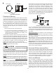
The installation must include a “P” style trap that is located
as close as is practical to the evaporator coil. See Conden-
sate Drain Trap figure for details of a typical condensate line
“P” trap.
NOTE: Trapped lines are required by many local codes. In
the absence of any prevailing local codes, please refer to
the requirements listed in the Uniform Mechanical Building
Code.
A drain trap in a draw-through application prevents air from
being drawn back through the drain line during fan opera-
tion thus preventing condensate from draining, and if con-
nected to a sewer line to prevent sewer gases from being
drawn into the airstream during blower operation.
Field experience has shown condensate drain traps with an
open vertical Tee between the air handler and the conden-
sate drain trap can improve condensate drainage in some
applications, but may cause excessive air discharge out of
the open Tee. Goodman® does not prohibit this type of
drain but we also do not recommend it due to the resulting
air leakage. Regardless of the condensate drain design used,
it is the installer’s responsibility to ensure the condensate
drain system is of sufficient design to ensure proper con-
densate removal from the coil drain pan.
Air Handler
3" MIN.
POSITIVE LIQUID
SEAL REQUIRED
AT TRAP
Drain
Connection
2" MIN.
Condensate Drain Trap
Use of a condensate removal pump is permitted when nec-
essary. This condensate pump should have provisions for
shutting off the control voltage should a blocked drain occur.
A trap must be installed between the unit and the conden-
sate pump.
IMPORTANT NOTE: The evaporator coil is coated with oils
that may dissolve styrofoam and certain types of plastics.
Therefore, a removal pump or float switch must not contain
any of these materials.
Tip: Priming the “P” trap may avoid improper draining at the
initial installation and at the beginning of the cooling season.
When coils are installed above ceilings, or in other locations
where damage from condensate overflow may occur, it is
MANDATORY to install a field fabricated auxiliary drain pan
under the coil cabinet enclosure. Drain lines from the auxil-
iary pan must be installed and terminated so that the home-
owner can see water discharges.
A
CHIEVING
2% L
OW
L
EAKAGE
R
ATE
Ensure that the Neoprene gasket with PSA remains intact
on all surfaces that the access panels are secured to. These
surfaces are the entire length of the wrapper and areas be-
tween the upper tie plate, upper and lower access panels.
Be sure that upper access panel breaker insert gasket is
intact and also flowrator gasket is installed on the lower ac-
cess panel. An additional drain hole cover is required.
C
IRCULATOR
B
LOWER
This air handler is equipped with a multi-speed circulator
blower. This blower provides ease in adjusting blower
speeds. The Specification Sheet applicable to your model
provides an airflow table, showing the relationship between
airflow (CFM) and external static pressure (E.S.P.), for the
proper selection of heating and cooling speeds. The heat-
ing blower speed is shipped set at “21 kW”, and the cooling
blower speed is set at “D”. These blower speeds should be