
Install Instructions


12
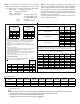
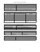
• Profile D ramps up to 50% of the demand for 1/2 minute,
then ramps to 82% of the full cooling demand airflow
and operates there for approximately 7 1/2 minutes.
The motor then steps up to the full demand airflow.
Profile D has a 1/2 minute at 50% airflow OFF delay.
OFF
OFF
S5
S6
S5
S6
S5
S6
S5
S6
OFF OFF OFF OFFON ON ON ON
Tap A Tap B Tap C Tap D*
Dipswitches - Cooling Airflow Ramping Profiles
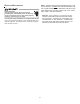
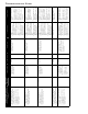
7. If an electric heater kit has been installed, determine
the heater kilowatt (kW) rating. Find the heater size in
the table below. Set dip switches 9, 10, and 11 for the
installed heater as shown in the Dipswitches - Electric
Heat Airflow figure below. The adjust setting (already
established by the cooling speed selection) also ap-
plies to the electric heater kit airflow. Thus, the electric
heater airflow is adjusted by the same amount. Verify
selected CFM by counting the green CFM LED blinks.
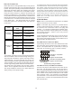
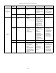
ELECTRIC HEAT TEMPERATURE RISE:
The heating mode temperature rise is dependent upon the
system airflow, the supply voltage, and the heat kit size (kW)
selected. Use the supply voltage/temperature rise tables
below to determine the temperature rise (
º
F).
3 5 6 8 10152021
60018283541
8001321263142
1000 11 17 21 25 34 50
1200 9 14 18 21 28 42 56 62
1400 8 12 15 18 24 36 48 53
1600 7 10 13 15 21 31 42 46
1800 6 9 12 14 19 28 37 41
2000 5 8 11 12 17 25 34 37
HEAT KIT NOMINAL kW
CFM
230/1/60 Supply Voltage - Temperature Rise Table °F
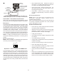
3 5 6 8 10152021
600 17 27 34 39
800 13 20 25 30 40
1000 10 16 20 24 32 48
1200 8 13 17 20 27 40 53 59
1400 7 11 14 17 23 34 46 51
1600 6 10 13 15 20 30 40 44
1800 6 9 11 13 18 27 36 39
2000 5 8 10 12 16 24 32 35
CFM
HEAT KIT NOMINAL kW
220/1/60 Supply Voltage - Temperature Rise Table °F
356810152021
600 16 25 32 37
800 12 19 24 38 38
1000 10 15 19 22 30 46
1200 8 13 16 19 25 38 51 56
1400 7 11 14 16 22 33 43 48
1600 6 9 12 14 19 28 38 42
1800 5 8 11 12 17 25 34 37
2000 5 8 10 11 15 23 30 34
CFM
HEAT KIT NOMINAL kW
208/1/60 Supply Voltage - Temperature Rise Table °F
S9
S10
OFF OFF OFF OFFON ON ON ON
21 kW* 20 kW
Electric Heating Air Flow (*indicates factory setting)
15 kW 10 kW
OFF OFF OFF OFFON ON ON ON
8 kW 6 kW 5 kW 3 kW
S11
S9
S10
S11
S9
S10
S11
S9
S10
S11
S9
S10
S11
S9
S10
S11
S9
S10
S11
S9
S10
S11
NOTE: Upon start up in communicating mode the circuit board will display a “1 Flash” error code on the diagnostic LED
and an “Ec” HTR TO LARGE error at the communicating display. This is an indication that the dip switches on the control
board need to be configured in accordance with the Electric Heating Airflow Table on the following page of this manual.
Configuring the dip switches and resetting power to the unit will clear the error code.