
Install Instructions


14
T
ROUBLESHOOTING
ELECTROSTATIC DISCHARGE (ESD) PRECAUTIONS
NOTE: Discharge body’s static electricity before touching
unit. An electrostatic discharge can adversely affect electrical
components.
Use the following precautions during air handler installation
and servicing to protect the integrated control module from
damage. By putting the air handler, the control, and the
person at the same electrostatic potential, these steps will
help avoid exposing the integrated control module to elec-
trostatic discharge. This procedure is applicable to both in-
stalled and uninstalled (ungrounded) blowers.
1. Disconnect all power to the blower. Do not touch the
integrated control module or any wire connected to the
control prior to discharging your body’s electrostatic
charge to ground.
2. Firmly touch a clean, unpainted, metal surface of the
modular blower near the control. Any tools held in a
person’s hand during grounding will be discharged.
3. Service integrated control module or connecting wiring
following the discharge process in step 2. Use caution
not to recharge your body with static electricity; (i.e., do
not move or shuffle your feet, do not touch ungrounded
objects, etc.). If you come in contact with an un-
grounded object, repeat step 2 before touching control
or wires.
4. Discharge your body to ground before removing a new
control from its container. Follow steps 1 through 3 if
installing the control on a blower. Return any old or
new controls to their containers before touching any
ungrounded object.
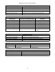
DIAGNOSTIC CHART
HIGHVOLTAGE!
T
O
AVOID
PERSONAL
INJURY
OR
DEATH
DUE
TO
ELECT RICAL
SHOCK
,
DISCONNECT
ELECT RICAL
POWER
BEFORE
PERFORMING
ANY
SERVICE
OR
MAINTENANCE
.
WARNING
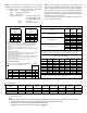
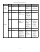
Refer to the Troubleshooting Chart at the end of this manual
for assistance in determining the source of unit operational
problems. The red diagnostic LED blinks to assist in trouble-
shooting the unit. The number of blinks refers to a specific
fault code.
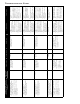
FAULT RECALL
The integrated control module is equipped with a momen-
tary push-button switch that can be used to display the last
six faults on the red diagnostic LED. The control must be in
Standby Mode (no thermostat inputs) to use the feature. De-
press the push-button for approximately two seconds and
less than five seconds. The LED display will then display
the six most recent faults beginning with the most recent
fault and decrementing to the least recent fault. The faults
may be cleared by depressing the button for greater than
five seconds.
NOTE: Consecutively repeated faults are displayed a
maximum of three times. Example: A clogged return air filter
causes the air handler’s motor to repeatedly enter a limiting
condition. The control will only store this fault the first three
consecutive times the fault occurs.
C
OMFORT
N
ET
™ S
YSTEM
OVERVIEW
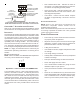
The ComfortNet system is a system that includes a
ComfortNet compatible air handler and air conditioner or heat
pump with a CTK0*AA thermostat. Any other system con-
figurations are considered invalid ComfortNet systems and
must be connected as a traditional (or non-communicating)
system (see Electrical).
A ComfortNet heating/air conditioning system differs from a
non-communicating/traditional system in the manner in which
the indoor unit, outdoor unit and thermostat interact with one
another. In a traditional system, the thermostat sends com-
mands to the indoor and outdoor units via analog 24 VAC
signals. It is a one-way communication path in that the in-
door and outdoor units typically do not return information to
the thermostat.
On the other hand, the indoor unit, outdoor unit, and ther-
mostat comprising a ComfortNet system “communicate” digi-
tally with one another. It is now a two-way communications
path. The thermostat still sends commands to the indoor
and outdoor units. However, the thermostat may also re-
quest and receive information from both the indoor and out-
door units. This information may be displayed on the
ComfortNet thermostat. The indoor and outdoor units also
interact with one another. The outdoor unit may send com-
mands to or request information from the indoor unit. This
two-way digital communications between the thermostat and
subsystems (indoor/outdoor unit) and between subsystems
is the key to unlocking the benefits and features of the
ComfortNet system.
Two-way digital communications is accomplished using only
two wires. The thermostat and subsystem controls are pow-
ered with 24 VAC Thus, a maximum of 4 wires between the
equipment and thermostat is all that is required to operate
the system.