
Install Instructions


15
AIRFLOW CONSIDERATION
Airflow demands are managed differently in a fully commu-
nicating system than they are in a non-communicating wired
system. The system operating mode (as determined by the
thermostat) determines which unit calculates the system
airflow demand. If the indoor unit is responsible for deter-
mining the airflow demand, it calculates the demand and
sends it to the ECM motor. If the outdoor unit or thermostat
is responsible for determining the demand, it calculates the
demand and transmits the demand along with a fan request
to the indoor unit. The indoor unit then sends the demand
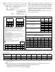
to the ECM motor. The table below lists the various
ComfortNet systems, the operating mode, and airflow de-
mand source.
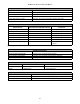
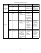
System
System Operating
Mode
Air fl ow De ma nd S ourc e
Cooling Air Conditioner
Heating Air Handler
Continuous Fan Thermostat
Cooling Heat Pump
Heat Pump Heating
Only
Heat Pump
HP + Electric Heat
Strips
> of Heat Pump or Air
Handler Demand
Electric Heat Strips
Only
Air Handler
Continuous Fan Thermostat
Air Conditioner +
Air Handler
He at Pump + Air
Handler
For example, assume the system is a heat pump matched
with an air handler. With a call for low stage cooling, the
heat pump will calculate the system’s low stage cooling
airflow demand. The heat pump will then send a fan
request along with the low stage cooling airflow demand
to the air handler. Once received, the air handler will send
the low stage cooling airflow demand to the ECM motor.
The ECM motor then delivers the low stage cooling
airflow. See the applicable ComfortNet air conditioner or
heat pump installation manual for the airflow delivered
during cooling or heat pump heating.
In continuous fan mode, the CTK0*AA thermostat provides
the airflow demand. The thermostat may be configured for a
low, medium, or high continuous fan speed. The low, medium,
and high fan speeds correspond to 25%, 50% and 75%,
respectively, of the air handlers’ maximum airflow capability.
During continuous fan operation, the thermostat sends a fan
request along with the continuous fan demand to the air
handler. The air handler, in turn, sends the demand to the
ECM motor. The ECM motor delivers the requested
continuous fan airflow.
CTK0*AA WIRING
NOTE: Refer to section Electrical Connections for 208/230
volt line connections to the air handler.
NOTE: A removable plug connector is provided with the
control to make thermostat wire connections. This plug may
be removed, wire connections made to the plug, and
replaced. It is strongly recommended that multiple wires
into a single terminal be twisted together prior to inserting
into the plug connector. Failure to do so may result in
intermittent operation.
Typical 18 AWG thermostat wire may be used to wire the
system components. One hundred (100) feet is the maxi-
mum length of wire between indoor unit and outdoor unit, or
between indoor unit and thermostat.
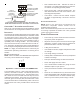
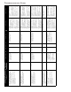
FOUR-WIRE INDOOR AND OUTDOOR WIRING
Typical wiring will consist of four wires between the indoor
unit and outdoor unit and between the indoor unit and ther-
mostat. The required wires are: (a) data lines, 1 and 2; (b)
thermostat “R” (24 VAC hot) and “C” (24 VAC common).
12RC
12RC
CTK0*AA
Thermostat
ComfortNet™ Compatible
Air Handler
Integrated Control Module
ComfortNet Compatible AC/HP
Integrated Control Module
12RC
System Wiring Using Four-Wires
TWO-WIRE OUTDOOR, FOUR-WIRE INDOOR WIRING
Two wires only may be utilized between the indoor and out-
door units. For this wiring scheme, only the data lines, 1
and 2, are required between the indoor and outdoor units. A
40VA, 208/230 VAC to 24 VAC transformer must be installed
in the outdoor unit to provide 24 VAC power to the outdoor
unit’s electronic control. The transformer is included with
the CTK0*AA kit. See kit instructions for mounting and wir-
ing instructions. Four wires are required between the indoor
unit and thermostat.