
Installation INstructions


11
12.4.2 Air Handler - Non-Circuit Breaker Heat Kits
A terminal block is provided with the HKS kit to attach the
power supply and air handler connections. Follow the HKS
Installation Manual and wiring diagram for complete wir-
ing details.
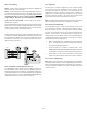
12.4.3 Air Handler With Circuit Breaker Heat Kit
The air handler has a plastic cover on the upper access panel
that will require either one or both sections to be removed
to allow the heat kit circuit breaker(s) to be installed. The
circuit breakers have lugs for power supply connection. See
the HKS Installation Instructions for further details.
12.5 Low Voltage Connections
Several combinations of low voltage schemes are possible,
depending on the presence of a heat kit and whether the
heat kit is single-stage or multi-stage, whether the outdoor
section is an air conditioner or heat pump, and whether
the system is setup with a communicating or traditional
thermostat. The 24V-control voltage connects the air han-
dler to the room thermostat and condenser. Low voltage
wiring must be copper conductors. A minimum of 18 AWG
must be used for installations up to 100 feet. Low voltage
wiring must be connected through the top of the cabinet
or either side. See the “Thermostat Wiring” section of this
manual for typical low voltage wiring connections.
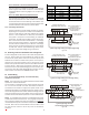
13 Achieving 1.4% and 2.0% Airflow Low Leakage Rate
Ensure all the gaskets remain intact on all surfaces as shipped with
the unit. These surfaces are areas between the upper tie plate
and coil access panel, blower access and coil access panels, and
between the coil access and filter access panels. Ensure upon in-
stallation, that the plastic breaker cover is sitting flush on the
blower access panel and all access panels are flush with each other
and the cabinet. With these requirements satisfied, the unit
achieves less than 1.4% airflow leakage @ 0.5 inch wc static pres-
sure and less than 2% airflow leakage @1inch wc static pressure
when tested in accordance with ASHRAE Standard 193.
14 24 Volt Wiring
14.1 24 Volt Thermostat Wiring - Non-Communicating
Thermostat Connections
NOTE: Wire routing must not interfere with the circulator blower
operation or routine maintenance.
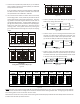
The air handler’s integrated control module provides terminals
for “Y1” and “Y2” and “W1” and “W2” thermostat connections.
This allows the air handler to support the systems shown in the
following table. Refer to the following figures for typical connec-
tions to the integrated control module. Thermostat wiring entrance
holes are located in the top of the blower. Wire routing must not
interfere with circulator blower operation or routine maintenance.
NOTE: A removable plug connector is provided with the control
to make thermostat wire connections. This plug may be removed,
wire connections made to the plug, and replaced. It is STRONGLY
recommended that you do not connect multiple wires into a single
terminal. Wire nuts are recommended to ensure one wire is used
for each terminal. Failure to do so may result in intermittent
operation.
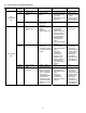
COOLING HEAT PUMP HEATING ELECTRIC HEATING
1-STAGE ------ 1- or 2-STAGE
2-STAGE ------ 1- or 2-STAGE
1-STAGE 1-STAGE ------
2-STAGE 2-STAGE ------
1-STAGE 1-STAGE 1- or 2-STAGE
2-STAGE 2-STAGE 1- or 2-STAGE
Table 7
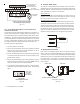
Air Handler Integrated
Control Module
Typical Single-Stage Cool,
Single-Stage Heat Thermostat
Dehumidistat
[Optional]
Remote Condensing Unit
(Single-Stage AC)
NEU
HOT
12RCG
W1 Y1 Y2
O
DEH UM
RCG
W1 Y1
RC
Y
Place Jumper Between Y1
and O for Proper
Dehumidification Operation
and Proper Ramping
Profile Operation
W2
Typical Single-Stage Cooling with Single-Stage Heating
Figure 14
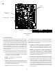
Air Handler Integrated
Control Module
Typical Two-Stage Cool,
Two-Stage Heat Thermostat
Dehumidistat
[Optional]
Remote Condensing Unit
(Two-Stage AC)
NEU
HOT
12RCG
W1 W2 Y1 Y2
O
DEH UM
RCG
W1 W2 Y1 Y2
RC
Y1 Y2
Place Jumper Between Y1
and O for Proper
Dehumidification Operation
and Proper Ramping
Profile Operation
Typical Two-Stage Cooling with Two-Stage Heating
Figure 15
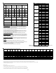
12RC
A
ir Handler
Integrated Control Module
Typical Single-Stage Cool,
Single-Stage Heat
Heat Pump Thermostat
Dehumidistat
[Optional]
G
W1 W2 Y1 Y2
O
DEH UM
Remote Condensing Unit
(Single-Stage HP)
NEU
HOT
W/E
RCG
Y1
O
RC
W1 Y
O
Typical Single-Stage Heat Pum
with Auxiliary/Emergency Heating
Figure 16