
Installation INstructions


17
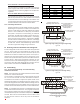
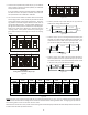
19.3 Fault Recall
The integrated control module is equipped with a momentary
push-button switch that can be used to display the last six faults
on the 7 segment LED display. The control must be in Standby
Mode (no thermostat inputs) to use the feature. Depress the
push-button for approximately two seconds and less than five sec-
onds. The LED display will then display the six most recent faults
beginning with the most recent fault and decrementing to the
least recent fault. The faults may be cleared by depressing the
button for greater than five seconds.
NOTE: Consecutively repeated faults are displayed a maximum
of three times. Example: A clogged return air filter causes the air
handler’s motor to repeatedly enter a limiting condition. The
control will only store this fault the first three consecutive times
the fault occurs.
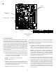
20 ComfortNet™ System
20.1 Overview
The ComfortNet system is a system that includes a ComfortNet
compatible air handler and air conditioner or heat pump with a
CTK0* thermostat. Any other system configurations are consid-
ered invalid ComfortNet systems and must be connected as a tra-
ditional (or non-communicating) system (see the 24 VOLT THERMO-
STAT WIRING - NON-COMMUNICATING THERMOSTAT CONNECTIONS section for
details).
A ComfortNet heating/air conditioning system differs from a non-
communicating/traditional system in the manner in which the in-
door unit, outdoor unit and thermostat interact with one another.
In a traditional system, the thermostat sends commands to the
indoor and outdoor units via analog 24 VAC signals. It is a one-
way communication path in that the indoor and outdoor units
typically do not return information to the thermostat.
On the other hand, the indoor unit, outdoor unit, and thermostat
comprising a ComfortNet system “communicate” digitally with
one another. It is now a two-way communications path. The
thermostat still sends commands to the indoor and outdoor units.
However, the thermostat may also request and receive informa-
tion from both the indoor and outdoor units. This information
may be displayed on the ComfortNet thermostat. The indoor and
outdoor units also interact with one another. The outdoor unit
may send commands to or request information from the indoor
unit. This two-way digital communications between the thermo-
stat and subsystems (indoor/outdoor unit) and between sub-
systems is the key to unlocking the benefits and features of the
ComfortNet system.
Two-way digital communications is accomplished using only two
wires. The thermostat and subsystem controls are powered with
24 VAC Thus, a maximum of 4 wires between the equipment and
thermostat is all that is required to operate the system.
20.1 Airflow Consideration
Airflow demands are managed differently in a fully communicat-
ing system than they are in a non-communicating wired system.
The system operating mode (as determined by the thermostat)
determines which unit calculates the system airflow demand. If
the indoor unit is responsible for determining the airflow de-
mand, it calculates the demand and sends it to the ECM motor. If
the outdoor unit or thermostat is responsible for determining the
demand, it calculates the demand and transmits the demand
along with a fan request to the indoor unit. The indoor unit then
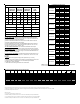
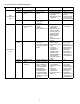
sends the demand to the ECM motor. The table below lists the
various ComfortNet systems, the operating mode, and airflow de-
mand source.
For example, assume the system is a heat pump matched with an
air handler. With a call for low stage cooling, the heat pump will
calculate the system’s low stage cooling airflow demand. The heat
pump will then send a fan request along with the low stage cool-
ing airflow demand to the air handler. Once received, the air han-
dler will send the low stage cooling airflow demand to the ECM
motor. The ECM motor then delivers the low stage cooling air-
flow. See the applicable ComfortNet air conditioner or heat pump
installation manual for the airflow delivered during cooling or heat
pump heating.
In continuous fan mode, the CTK0* thermostat provides the
airflow demand. Depending on which CTK0* thermostat has been
installed three or four continuous fan speeds may be available. If
the thermostat provides three speeds (low, medium, high) they
correspond to 25%, 50% and 75%, respectively, of the air handlers’
maximum airflow capability. If the thermostat provides four
continuous fan speeds then a 100% airflow option is added.
During continuous fan operation, the thermostat sends a fan
request along with the continuous fan demand to the air handler.
The air handler, in turn, sends the demand to the ECM motor. The
ECM motor delivers the requested continuous fan airflow.
Sys te m
Sys te m
Operating Mode
Airflow Dem and
Source
Cooling Air Conditioner
Heating Air Handler
Continuous Fan Thermostat
Cooling Heat Pump
Heat Pump Heating
Only
Heat Pump
HP + Electric Heat
Strips
> of Heat Pump or Air
Handler Demand
Electric Heat Strips
Only
Air Handler
Continuous Fan Thermostat
Air Conditioner +
Air Handler
Heat Pump + A ir
Handler
Figure 32