
AVPTC Service Manual
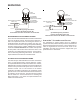


SERVICING
38
ComfortNet ™
Thermostat Only
Symptoms of Abnormal Operation
(Communicating & Non-communicating
Thermostat)
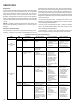
Diagnostic/Status
LED Codes
Fault Description
Message Code
Possible Causes Corrective Actions Notes & Cautions
x LED display is ON continuously
ON
x Normal operation
None None
x Normal operation x None x Normal operation
x Electric heaters fail to energize on a call for
W1 or Auxiliary/Emergency heat
x Integrated control module LED display
provides the indicated error code.
x ComfortNet thermostat “Call for Service”
icon illuminated
x ComfortNet thermostat scrolls “Check Air
Handler” message
1 Flash
x Heater kit selected via
dipswitches is too large
for heater kits specified
in shared data set
HTR TOO
LARGE
Ec
x Heater kit selected via
dipswitches is too large for heater
kits in shared data set
x Verify electric heat dipswitch
settings
x Verify the installed electric
heater is valid for the air handler.
Check nameplate or
Specification Sheet applicable to
your model* for allowable heater
kit(s).
x Verify shared data set is correct
for the specific model. Re-
populate data using correct
memory card if required.
x Turn power OFF prior to repair.
x Use memory card for the specific
model.
x Insert memory card BEFORE
turning power ON. Memory card
may be removed after data is
loaded.
x Turn power OFF before removing
memory card.
x Error code will be cleared once
data is loaded.
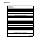
x Electric heat airflow is higher than
expected on a call for W1 or
Auxiliary/Emergency heat
x Integrated control module LED display
provides the indicated error code.
1 Flash
x Heater kit selected via
dipswitches is too small
for heater kits specified
in shared data set
HTR TOO
SMALL
Ec
x Heater kit selected via
dipswitches is too small for heater
kits in shared data set
x Verify electric heat dipswitch
settings
x Verify the installed electric
heater is valid for the air handler.
Check nameplate or
Specification Sheet applicable to
your model* for allowable heater
kit(s).
x Verify shared data set is correct
for the specific model. Re-
populate data using correct
memory card if required.
x Turn power OFF prior to repair.
x Use memory card for the specific
model.
x Insert memory card BEFORE
turning power ON. Memory card
may be removed after data is
loaded.
x
x Turn power OFF before removing
memory card.
x Error code will be cleared once
data is loaded.
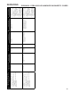
x Electric heat airflow is higher than
expected on a call for W1 or
Auxiliary/Emergency heat
x Integrated control module LED display
provides the indicated error code.
1 Flash
x Heater kit selected via
dipswitches does not
heater kits specified in
shared data set
NO HTR
MATCH
Ec
x Heater kit selected via
dipswitches is doesn’t match
heater kits in shared data set
x Verify electric heat dipswitch
settings
x Verify the installed electric
heater is valid for the air handler.
Check nameplate or
Specification Sheet applicable to
your model* for allowable heater
kit(s).
x Verify shared data set is correct
for the specific model. Re-
populate data using correct
memory card if required.
x Turn power OFF prior to repair.
x Use memory card for the specific
model.
x Insert memory card BEFORE
turning power ON. Memory card
may be removed after data is
loaded.
x Turn power OFF before removing
memory card.
x Error code will be cleared once
data is loaded.
x No air handler operation.
x Integrated control module LED display
provides the indicated error code.
x ComfortNet thermostat displays “Battery
Power”
5 Flashes
x Open Fuse
Not
Displayed
Not
Displayed
x Short in low voltage wiring x Locate and correct short in low
voltage wiring
x Turn power OFF prior to repair.
x Replace fuse with 3-amp
automotive type
x Air handler fails to operate
x Integrated control module LED display
provides no signal.
x ComfortNet thermostat “Call for Service”
icon illuminated
x ComfortNet thermostat scrolls “Check Air
Handler” message
None
x No 208/230 volt power
to air handler or no 24
volt power to integrated
control module
x Blown fuse or circuit
breaker
x Integrated control
module has an internal
fault.
INTERNAL
FAULT
EE
x Manual disconnect switch OFF or
24 volt wire improperly
connected or loose
x Blown fuse or circuit breaker
x Integrated control module has an
internal fault
x Assure 208/230 volt and 24 volt
power to air handler and
integrated control module.
x Check integrated control module
fuse (3A). Replace if necessary.
x Check for possible shorts in
208/230 volt and 24 volt circuits.
Repair as necessary.
x Replace bad integrated control
module.
x Turn power OFF prior to repair.
x Replace integrated control
module fuse with 3A automotive
fuse.
x Replace integrated control
module with correct replacement
part
x Read precautions in “Electrostatic
Discharge” section of manual.
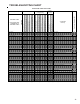
PCBJA101- PCBJA102 AIR HANDLER DIAGNOSTIC CODES