
AVPTC Service Manual


SERVICING
64
1
2
3
4
5
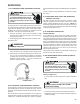
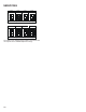
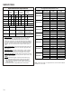
Lines 1 and 2 will be connected
for 12OVAC Power Connector
applications only
Gnd
AC Line Connection
AC Line Connection
}
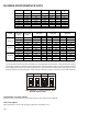
5. Measure voltage between pins 4 and 3. Voltage should
be approximately half of the voltage measured in step 4.
6. Measure voltage between pins 5 and 3. Voltage should
be approximately half of the voltage measured in step 4.
7. If no voltage is present, check supply voltage to air handler
or modular blower. See section S-1.
8. Disconnect power to air handler or modular blower.
Reconnect the 5-circuit power harness disconnected in
step 2.
Electrical Checks - Low Voltage Control Circuits
1. Turn on power to air handler or modular.
WARNING
Line Voltage now present.
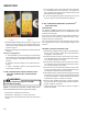
2. Check voltage between pins on the 4-wire motor control
harness between themotor and control board.
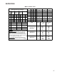
3. Voltage on pins should read:
Pins 1 to 4 = 5.0vdc
Pins 2 to 4 = 2.5vdc
Pins 3 to 4 = 2.5vdc
Pins 2 to 3 = 0.3vdc
Motor Control/End Bell Checks
HIGH VOLTAGE!
Disconnect ALL power before servicing
or installing. Multiple power sources
may be present. Failure to do so may
cause property damage, personal injury
or death.
1. Disconnect power to air handler or modular blower.
NOTE: Motor contains capacitors that can hold a charge for
several minutes after disconnecting power. Wait 5 minutes
after removing power to allow capacitors to discharge.
2. Disconnect the motor control harness and motor power
harness.
3. Remove the blower assembly from the air handler or
modular blower.
4. Remove the (3) screws securing the control/end bell to
the motor. Separate the control/end bell. Disconnect
the 3-circuit harness from the control/end bell to remove
the control/end bell from the motor.
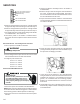
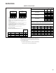
5. Inspect the NTC thermistor inside the control/end bell
(see figure below). Replace control/end bell if thermistor
is cracked or broken.
6. Inspect the large capacitors inside the control/end bell
(see figure below). Replace the control/end bell if any of
the capacitors are bulging or swollen.
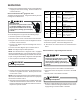
7. Locate the 3-circuit connector in the control/end bell.
Using an ohmmeter, check the resistance between each
terminal in the connector. If the resistance is 100 Ω or
greater, the control/end bell is functioning properly.
Replace the control/end bell if the resistance is lower
than 100 Ω.
8. Reassemble motor and control/end bell in reverse of
disassembly. Replace blower assembly into air handler
or modular blower.