
AWST Installation Manual


6
9.1 Low Voltage Connections
Several combinations of low voltage schemes are possible,
depending on the presence of a heat kit and whether the
heat kit is single-stage or multi-stage, whether the outdoor
section is an air conditioner or heat pump, and whether
the outdoor section is single-stage or two stage. The
24V-control voltage connects the air handle to the room
thermostat and condenser. Low voltage wiring must be
copper conductors. A minimum of 18AWG must be used
for installations. Low voltage wiring must be connected
through the top of the cabinet or either side. See the
“Thermostat Wiring” section of this manual for typical low
voltage wiring connections.
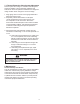
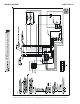
ELECTRICAL POWER
SUPPLY
OFFSET HANGING
BRACKET
STUD
LOW VOLTAGE
POWER SUPPLY
B
D
SUCTION LINE
COPPER CAP IS INSTALLED
ON MANIFOLD SUCTION AND LIQUID TUBE
C
LIQUID LINE
PULL OUT DISCONNECT
ATTACHMENT
HOLES
E
REMOVABLE
SERVICE DOOR
A
LOWER FRONT
ACCESS PANEL
AIR FILTER
FRONT RETURN FILTER
LARGE CHASIS
A 36 36
B 24 20 3/16
C 21 16 1/8
D 19 7/8 16
E 15 7/8 11
CABINET DIMENSIONS
2.5 & 3.0 TON
SMALL CHASSIS
6
BOTTOM PRIMARY AND SECONDARY
DRAINS CAN BE ACCESSED THROUGH THE
BOTTOM OF THE UNIT. (3/4" NPT FEMALE
CONNECTION)
NOTE: HAND TIGHTEN ONLY
SUCTION LINE
SMALL CHASSIS
REMOVABLE
SERVICE DOOR
LIQUID LINE
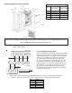
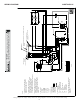
R G W C
Thermostat
Air Handler
Condensing Unit
#18 Gauge
24 VAC
#18 Gauge
24 VAC
Y R G W
C Y
Y
Note: Connect T2, T3, or T4 to the Y
terminal to the outdoor unit. See Table
below for correct CFM selection
Note: Tape the T5 brown wire
T1
T5
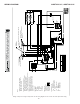
R
G W
C
Thermostat
Air Handler
Condensing Unit
#18 Gauge
24 VAC
#18 Gauge
24 VAC
Y R G W
C Y
Y
FC = Field Connection
AWST 18,24,30,36
AWUF 18, 24, 30, 36, 37
AWUT 24, 37
LARGE CHASSIS
2.5 & 3.0 TON
SMALL CHASSIS
1.0, 1.5, & 2.0 TON
A 36 36
B 24 20 3/16
C 21 16 1/8
D 19 7/8 16
E 15 7/8 11
CABINET DIMENSIONS
NOTE: SPECIFICATIONS & PERFORMANCE DATA LISTED HEREIN ARE SUBJECT TO CHANGE WITHOUT NOTICE
NOTE: Thermostat heat anticipator setting is 0.2.
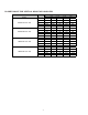
WIRE COLOR BTUH NOMINAL CFM
PURPLE 18,000 600
PINK
(
ONLY AVAILABLE FOR AWUF19 MODELS
)
12,000 480
PINK 24,000 800
YELLOW 30,000 950
NOTE: Connect appropriate speed tap (Pink/Purple/Yellow) to Y. Refer to table below for speed tap
selection. It is not recommended to use the 1 Ton application for AWUF19 8kW heater models.
NOTE: Connect appropriate speed tap (Pink/Purple/Yellow) to Y. Refer to table below for speed tap
selection. It is not recommended to use the 1 Ton application for AWST18 8kW heater models.
9 Wiring Diagrams and Air Flow Data
TAP COLOR
T1 GREEN
T2 PURPLE
T3 PINK
T4 YELLOW
T5 WHITE