
CAPFA Installation Manual


2
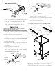
7. Condensate Drain Piping
In all cooling applications where condensate overflow may cause
damage, a secondary drain pan must be provided by the installer
and placed under the entire unit with a separate drain line prop-
erly sloped and terminated in an area visible to the owner. This
secondary drain pan can provide extra protection to the area
under the unit should the primary drain plug up and overflow. As
expressed in our product warranty, we will not be liable for any
damages, structural or otherwise due to the failure to follow this
installation requirement.
Condensate drain connections are located in the drain pan at the
bottom of the coil/enclosure assembly. Use the female (3/4” FPT)
threaded fitting that protrudes outside of the enclosure for exter-
nal connections. The connectors required are 3/4" NPT male, ei-
ther PVC or metal pipe, and must be hand tightened to a torque of
no more than 37 in-lbs. to prevent damage to the drain pan con-
nection. An insertion depth between .36 to .49 inches (3-5 turns)
should be expected at this torque.
1. Ensure drain pan hole is NOT obstructed.
2. To prevent potential sweating and dripping on finished space,
it may be necessary to insulate the condensate drain line
located inside the building. Use Armaflex
®
or similar mate-
rial.
A Secondary Condensate Drain Connection, now called for by many
building codes, has been provided. Pitch the drain line 1/4" per
foot to provide free drainage. Provide required support to drain
line to prevent bowing. Install a condensate trap in the primary
drain line to ensure proper drainage. If the secondary drain line
is required, run the line separately from the primary drain and
end it where condensate discharge can be easily seen.
CAUTION
I
F
SECONDARY
DRAIN
IS
NOT
INSTALLED
,
THE
SECONDARY
ACCESS
MUST
BE
PLUGGED
.
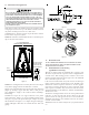
8. Refrigerant Lines
CAUTION
T
HE
COIL
IS
SHIPPED
UNDER
PRESSURE
WITH
AN
R-410A
GAS
MIXTURE
. U
SE
APPROPRIATE
SERVICE
TOOLS
AND
FOLLOW
THESE
INSTRUCTIONS
TO
PREVENT
INJURY
.
A
QUENCHING
CLOTH
IS
STRONGLY
RECOMMENDED
TO
PREVENT
SCORCHING
OR
MARRING
OF
THE
EQUIPMENT
FINISH
WHEN
BRAZING
CLOSE
TO
THE
PAINTED
SURFACES
. U
SE
BRAZING
ALLOY
OF
5%
MINIMUM
SILVER
CONTENT
.
NOTE: Refrigerant tubing must be routed to allow adequate ac-
cess for servicing and maintenance of the unit.
Do not handle coil assembly with manifold or flowrator tubes.
Doing so may result in damage to the tubing joints. Always use
clean gloves for handling coil assemblies.
8.1 Tubing Size/Length
For the correct tubing size, follow the specification for the
condenser/heat pump. Give special consideration to minimiz-
ing the length of refrigerant tubing when installing coils. Refer
to Remote Cooling/Heat Pump Technical Publication TP-107*
Long Line Set Application R-410A for guidelines for line lengths
over 80’. Leave a minimum 3" straight in line set from braze
joints before any bends.
8.2Tubing Preparation
All cut ends are to be round, burr free, and cleaned. Any other
condition increases the chance of a refrigerant leak. Use a
pipe cutter to remove the closed end of the spun closed suction
line.
8.3Brazing
Braze joints should be made only with the connections pro-
vided external to the cabinet. Do not alter the cabinet nor
braze inside the cabinet. To avoid overheating after brazing,
quench all brazed joints with water or a wet rag.
A
PPLYING
TOO
MUCH
HEAT
TO
ANY
TUBE
CAN
MELT
THE
TUBE
. T
ORCH
HEAT
REQUIRED
TO
BRAZE
TUBES
OF
VARIOUS
SIZES
MUST
BE
PROPORTIONAL
TO
THE
SIZE
OF
THE
TUBE
.
S
ERVICE
PERSONNEL
MUST
USE
THE
APPROPRIATE
HEAT
LEVEL
FOR
THE
SIZE
OF
THE
TUBE
BEING
BRAZED
.
8.4Special Instructions for Flowrator (Piston) Version
Coils in flowrator version are equipped with a check style
flowrator for refrigerant management. For most installations
with matching applications, no change to the flowrator piston
is required. However, in mix-matched applications, a piston
change may be required. See the piston kit chart or consult
your local distributor for details regarding mix-matched pis-
ton sizing. If the mix-matched application requires a different
piston size, change the piston in the distributor on the indoor
coil before installing the coil and follow the procedure shown
below.
8.5Tubing Connections for Flowrator Model
1. Loosen the 13/16 nut 1 TURN ONLY to allow high pressure
tracer gas to escape. No gas indicates a possible leak.
2. After the gas has escaped, remove the nut and discard the
plastic or brass cap.
3. Remove the check piston to verify it is correct and then re-
place the piston. See piston kit chart in instructions.
4. Use a tube cutter to remove the spin closure on the suc-
tion line. DO NOT USE A CUTTING METHOD THAT WOULD
RESULT IN THE GENERATION OF COPPER SHAVINGS OR
COPPER DUST.
5. Slide the 13/16 nut into place on the tailpiece supplied in
the literature bag or with the unit.
6. Insert liquid line into the supplied tailpiece.