
CAPFA Installation Manual


3
Figure 1
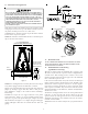
7. Insert the suction line into the connection, slide the insula-
tion and the rubber grommet at least 18" away from the
braze joint. Braze both liquid and suction line joints.
8. AFTER THE TAILPIECE HAS COOLED, confirm position of the
white Teflon
®
seal and hand tighten the 13/16 nut.
E
XCESSIVE
TORQUE
CAN
CAUSE
ORIFICES
TO
STICK
. U
SE
THE
PROPER
TORQUE
SETTINGS
WHEN
TIGHTENING
ORIFICES
.
CAUTION
9. Torque the 13/16” nut to 10-20 ft-lbs. or 1/6 turn past hand
tight.
10. Replace suction line grommet and insulation.
8.6 Tubing Connections for TXV Version
TXV models come with factory installed non-adjustable TXV
with the bulb permanently located on the suction tube.
1. Remove coil access panel.
2. Remove access valve fitting cap and depress the valve stem
in access fitting to release pressure. No pressure indicates
possible leak.
3. Replace the refrigerant tubing panel.
4. Remove the spin closure on both the liquid and suction
tubes using a tubing cutter. DO NOT USE A CUTTING
METHOD THAT WOULD RESULT IN THE GENERATION OF
COPPER SHAVINGS OR COPPER DUST.
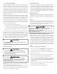
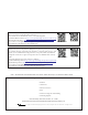
SUCTION
LINE SET
SUCTION
TUBE
RUBBER
GROMMET
Figure 2.1
LIQUID
LINE SET
LIQUID
LINE
RUBBER
GROMMET
Figure 2.2
5. Insert liquid line set into liquid tube expansion and slide
grommet about 18" away from braze joint.
6. Insert suction line set into suction tube expansion and slide
insulation and grommet about 18" away from braze joint.
7. Braze suction and liquid line joints.
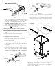
9. Top flanges can be bent for ease in installation to the
duct flanges.
Unfolded View
Top Flange Detail View
FILLER
PLATE
Figure 3
10. Filler Plates
Filler plates are supplied on all 17.5, 21, & 24.5 inch chassis to be
used for adapting the unit to a furnace one size smaller. If the
plenum and furnace openings are the same size, the filler plates
must be removed. See Figure 3.