
DSZC16 Installation Manual


10
CTK0* WIRING
NOTE: Refer to section Electrical Connections - High Voltage Connections for 208/230 volt line connections to the air conditioner
or heat pump.
NOTE: A removable plug connector is provided with the control to make thermostat wire connections. This plug may be
removed, wire connections made to the plug, and replaced. It is strongly recommended that you do not connect multiple wires
into a single terminal. Wire nuts are recommended to ensure one wire is used for each terminal. Failure to do so may result in
intermittent operation.
Typical 18 AWG thermostat wire may be used to wire the system components. However, communications reliability may be
improved by using a high quality, shielded, twisted pair cable for the data transmission lines. In either case, 150 feet is the
maximum length of wire between indoor unit and outdoor unit, or between
indoor unit and thermostat.
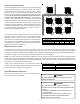
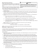
FOUR-WIRE I NDOOR AND OUTDOOR W IRING
Typical wiring will consist of 4 wires between the indoor unit and outdoor
unit and between the indoor unit and thermostat. The required wires are: (a)
data lines, 1 and 2; (b) thermostat “R” (24 VAC hot) and “C” (24 VAC com-
mon).
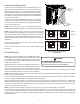
TWO-WIRE OUTDOOR, FOUR-WIRE INDOOR W IRING
Two wires only may be utilized between the indoor and out-
door units. For this wiring scheme, only the data lines, 1
and 2, are required between the indoor and outdoor units. A
40VA, 208/230 VAC to 24 VAC transformer must be installed
in the outdoor unit to provide 24 VAC power to the outdoor
unit’s electronic control. CTK0* manual will state if this trans-
former is optional or mandatory. Four wires are required be-
tween the indoor unit and thermostat.
NOTE: Use of the CTK0* transformer is recommended if
installing a dual fuel system. Failure to use the transformer
in the outdoor unit could result in over loading of the furnace
transformer.
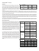
COMFORTNET™ SYSTEM ADVANCED F EATURES
The ComfortNet system permits access to additional sys-
tem information, advanced setup features, and advanced di-
agnostic/troubleshooting features. These advanced features are organized into a menu structure. See thermostat installation
manual for directions on how to access the ComfortNet User Menus. See following tables for menu layout.
CONFIGURATION
The configuration menu provides functional information about the installed equipment. System tonnage and number of cooling
and heating stages are displayed within this menu. A tonnage check will help determine if the equipment shared data is correct
for the unit. If the tonnage is not correct, even though very rare, a memory card is available to load the proper data.
DIAGNOSTICS
Accessing the air conditioner/heat pump’s diagnostics menu provides ready access to the last six faults detected by the air
conditioner/heat pump. Faults are stored most recent to least recent. Any consecutively repeated fault is stored a maximum
of three times. Example: The power supply to the air conditioner/heat pump is continuously below 187 VAC. The control will
only store this fault the first three consecutive times the fault occurs.
NOTE: It is highly recommended that the fault history be cleared after performing maintenance or servicing the heat pump.
12RC
12RC
CTK0*
Thermostat
CT Compatible
Air Handler/Furnace/Modular Blower
Integrated Control Module
CT Compatible AC/HP
Integrated Control Module
12RC
System Wiring Using Four-Wires
12RC
12RC
CTK0*
Thermostat
CT Compatible Air
Handler/Furnace/Modular
Blower Integrated
Control Module
CT Compatible
AC/HP Integrated
Control Module
40VA Transformer (included in
CTK0* kit)
208/230 VAC
24 VAC
12RC
System Wiring using Two-Wires between Furnace
and AC/HP and Four-Wires between Furnace
and Thermostat