
DSZC16 Installation Manual


2
I
NSTALLATION
C
LEARANCES
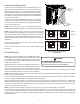
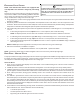
Special consideration must be given to location of the condensing
unit(s) in regard to structures, obstructions, other units, and any/
all other factors that may interfere with air circulation. Where
possible, the top of the unit should be completely unobstructed;
however, if vertical conditions require placement beneath an ob-
struction there should be a minimum of 60 inches between
the top of the unit and the obstruction(s). The specified di-
mensions meet requirements for air circulation only. Consult all
appropriate regulatory codes prior to determining final clearances.
Another important consideration in selecting a location for the
unit(s) is the angle to obstructions. Either side adjacent the valves
can be placed toward the structure provided the side away from
the structure maintains minimum service clearance. Corner in-
stallations are strongly discouraged.
This unit can be located at ground floor level or on flat roofs. At
ground floor level, the unit must be on a solid, level foundation
that will not shift or settle. To reduce the possibility of sound
transmission, the foundation slab should not be in contact with or
be an integral part of the building foundation. Ensure the founda-
tion is sufficient to support the unit. A concrete slab raised above
ground level provides a suitable base.
R
OOFTOP
I
NSTALLATIONS
If it is necessary to install this unit on a roof structure, ensure the roof structure can support the weight and that proper
consideration is given to the weather-tight integrity of the roof. Since the unit can vibrate during operation, sound vibration
transmission should be considered when installing the unit. Vibration absorbing pads or springs can be installed between the
condensing unit legs or frame and the roof mounting assembly to reduce noise vibration.
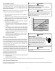
NOTE: These units require special location consideration in areas of heavy snow accumulation and/or areas with prolonged
continuous subfreezing temperatures. Heat pump unit bases have cutouts under the outdoor coil that permit drainage of frost
accumulation. Situate the unit to permit free unobstructed drainage of the defrost water and ice. A minimum 3” clearance under
the outdoor coil is required in the milder climates.
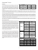
In more severe weather locations, it is recommended that the
unit be elevated to allow unobstructed drainage and air flow. The
elevation minimums at right are recommended:
S
AFE
R
EFRIGERANT
H
ANDLING
While these items will not cover every conceivable situation,
they should serve as a useful guide.
OK!
OK!
AA AAA
A
CC
C
C
OK!
OK!
OK!
OK!
NOT
RECOMMENDED
AA
AA
AA
AA
AA
B B B
B
Model Type A B C AA
Residential
10" 10" 18" 20"
Light Commercial
12" 12" 18" 24"
Minimum Airflow Clearance
Design Temperature Suggested Minimum Elevation
+15° and above 2 1/2"
-5° to +14° 8"
below -5° 12"
T
O
AVOID
POSSIBLE
INJURY
,
EXPLOSION
OR
DEATH
,
PRACTICE
SAFE
HANDLING
OF
REFRIGERANTS
.
WARNING
T
O
AVOID
POSSIBLE
EXPLOSION
,
USE
ONLY
RETURNABLE
(
NOT
DISPOSABLE
)
SERVICE
CYLINDERS
WHEN
REMOVING
REFRIGERANT
FROM
A
SYSTEM
.
• E
NSURE
THE
CYLINDER
IS
FREE
OF
DAMAGE
WHICH
COULD
LEAD
TO
A
LEAK
OR
EXPLOSION
.
• E
NSURE
THE
HYDROSTATIC
TEST
DATE
DOES
NOT
EXCEED
5
YEARS
.
• E
NSURE
THE
PRESSURE
RATING
MEETS
OR
EXCEEDS
400
PSIG
.
W
HEN
IN
DOUBT
,
DO
NOT
USE
CYLINDER
.
WARNING