
DSZC16 Installation Manual


6
L
OW
V
OLTAGE
C
ONNECTIONS
Condensing unit control wiring requires a nominal 24 VAC (+/- 6
VAC), 60 Hz, minimum 25 VA service from either the indoor or an
optional outdoor transformer. Low voltage wiring for the condens-
ing units depends on the thermostat used. The unit is designed to
work as part of a fully communicating HVAC system utilizing the
ComfortNet™ CTK0* thermostat, ComfortNet™ compatible indoor
unit, and up to four wires.
The unit also has legacy 24 VAC inputs to support non-communi-
cating systems. Route control wires through the low voltage port
and terminate in accordance with the wiring diagram provided in-
side the control panel cover.
NOTE: For two-stage units, refer to the Installation Instructions
supplied with the variable speed indoor units for field wiring connections.
NOTE: If the heat pump unit is wired in the communicating mode together
with a compatible communicating indoor unit and CTK0* communicating
thermostat, then the communicating thermostat is able to search and identify
the condensing unit when power is applied to the system. Refer to the
Installation Manual of the optional communicating thermostat for more
information.
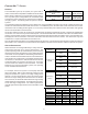
Use the dipswitch to select defrost time interval (30, 60, 90, 120
minutes; see chart below).
Factory default setting is 30 minutes. The maximum defrost cycle time is
10 minutes.
S
YSTEM
S
TART
U
P
NOTE: Power must be supplied to the 18 SEER outdoor units
containing ECM motors before the power is applied to the indoor
unit. Sending a low voltage signal without high voltage power
present at the outdoor unit can cause malfunction of the control
module on the ECM motor.
Adequate refrigerant charge for the matching evaporator coil or
air handler and 15 feet of lineset is supplied with the condens-
ing unit. If using evaporator coils or air handlers other than
HSVTC coil it maybe necessary to add or remove refrigerant to attain proper charge. If line set exceeds 15 feet in length,
refrigerant should be added at .6 ounces per foot of liquid line.
NOTE: Charge should always be checked using superheat when using a piston and subcooling when using TXV equipped
indoor coil to verify proper charge.
Open the suction service valve first! If the liquid service valve is opened first, oil from the compressor may be drawn into the indoor
coil TXV, restricting refrigerant flow and affecting operation of the system.
When opening valves with retainers, open each valve only until the top of the stem is 1/8” from the retainer. To avoid loss of
refrigerant, DO NOT apply pressure to the retainer. When opening valves without a retainer remove service valve cap and insert
a hex wrench into the valve stem and back out the stem by turning the hex wrench counterclockwise. Open the valve until it
contacts the rolled lip of the valve body.
NOTE: These are not back-seating valves. It is not necessary to force the stem tightly against the rolled lip.
After the refrigerant charge has bled into the system, open the liquid service valve. The service valve cap is the secondary seal
for the valve and must be properly tightened to prevent leaks. Make sure cap is clean and apply refrigerant oil to threads and
sealing surface on inside of cap. Tighten cap finger-tight and then tighten additional 1/6 of a turn (1 wrench flat) to properly seat
the sealing surfaces.
60
30
0
30 Minutes
60
60
30
0
60 Minutes
60
120 Minutes
60
30
0
90 Minutes
60
60
30
0
60
Dipswitch Settings for Selection
of Defrost Time
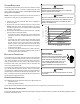
POSSIBLE REFRIGERANT LEAK!
T
O
AVOID
A
POSSIBLE
REFRIGERANT
LEAK
,
OPEN
THE
SERVICE
VALVES
UNTIL
THE
TOP
OF
THE
STEM
IS
1/8”
FROM
THE
RETAINER
.
CAUTION
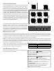
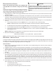
HIGH
VOLTAGE
PORT
LOW
VOLTAGE
PORT
Voltage Ports