
DSZC16 Installation Manual


8
E
XPANSION
V
ALVE
S
YSTEM
NOTE: Units matched with indoor coils equipped with
non-adjustable TXV should be charged by subcooling
only.
Run the unit on low stage cooling for 10 minutes until refriger-
ant pressures stabilize. Use the following guidelines and meth-
ods to check unit operation and ensure that the refrigerant
charge is within limits. Charge the unit on low stage.
1. Purge gauge lines. Connect service gauge manifold to base-valve service ports. Run system at least 10 minutes to allow
pressure to stabilize.
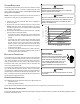
2. Temporarily install a thermometer on the liquid line at the liquid line service valve and 4-6" from the compressor on the
suction line. Ensure the thermometer makes adequate contact and is insulated for best possible readings. Use liquid line
temperature to determine subcooling and vapor temperature to determine superheat.
3. Check subcooling and superheat. Systems with TXV application should have a subcooling of 5 to 7°F and superheat of
7 to 9 °F.
a. If subcooling and superheat are low, adjust TXV to 7 to 9 ºF superheat, then check subcooling.
NOTE: To adjust superheat, turn the valve stem clockwise to increase and counter clockwise to decrease.
b. If subcooling is low and superheat is high, add charge to raise subcooling to 5 to 7 °F then check superheat.
c. If subcooling and superheat are high, adjust TXV valve to 7 to 9 ºF superheat, then check subcooling.
d. If subcooling is high and superheat is low, adjust TXV valve to 7 to 9 ºF superheat and remove charge to lower the
subcooling to 5 to 7 ºF.
NOTE: Do NOT adjust the charge based on suction pressure unless there is a gross undercharge.
4. Disconnect manifold set, installation is complete.
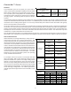
SUBCOOLING FORMULA = SAT. LIQUID TEMP. - LIQUID LINE TEMP.
NOTE: Check the Schrader ports for leaks and tighten valve cores if necessary. Install caps finger-tight.
H
EAT
P
UMP
- H
EATING
C
YCLE
The proper method of charging a heat pump in the heat mode is by weight with the additional charge adjustments for line size,
line length, and other system components. For best results on outdoor units with TXVs, superheat should be 2-5° at 4-6" from
the compressor. Make final charge adjustments in the cooling cycle.
ADDITIONAL N OTES
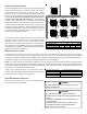
1. There are (3) 7-segment LED displays on the PCB. Refer to the Troubleshooting chart at the end of this manual for
definitions of the LED status.
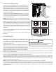
2. “TERM” dip switch is used for communications bus configuration. Leave the settings to the factory default position.
3. “LEARN” push button is used in communication mode to support device recognition on start-up. As the communication
system supports automatic identification of both indoor unit and outdoor unit, this button is not used for a normal start-up.
4. Press “TEST” push button, during system “Standby” mode to turn on both the compressor and outdoor fan for five
seconds.
5. The “RECALL” push button is used to retrieve the six most recent faults. The control must be in Standby Mode (no
thermostat inputs) to use the feature. Depress the push button for approximately two seconds and less than five seconds.
The 7-segment LED displays will then display the six most recent faults beginning with the most recent fault and
decrementing to the least recent fault. The faults may be cleared by depressing the button for greater than five seconds.
Consecutively repeated faults are displayed a maximum of three times. Refer to the fault code definitions at the end of
this manual for more details.
6. A forced defrost can be initiated by pressing “TEST” and “RECALL” push buttons simultaneously for more than 1 second
with a valid call for heat. The forced defrost can be terminated by
• A 10 minute lapse in time,
• A coil temperature rise above 75°F or
• By pressing the two buttons again for more than 1 second.
T
O
PREVENT
PERSONAL
INJURY
,
CAREFULLY
CONNECT
AND
DISCONNECT
MANIFOLD
GAUGE
HOSES
. E
SCAPING
LIQUID
REFRIGERANT
CAN
CAUSE
BURNS
. D
O
NOT
VENT
REFRIGERANT
INTO
THE
ATMOSPHERE
. R
ECOVER
ALL
REFRIGERANT
DURING
SYSTEM
REPAIR
AND
BEFORE
FINAL
UNIT
DISPOSAL
.
CAUTION