
GC9S96 Installation Manual
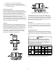
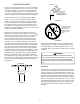
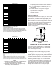
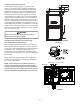

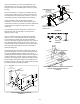


Table Of Contents
- Safety Considerations
- Electrostatic Discharge (ESD) Precautions
- To The Installer
- Product Application
- Location Requirements & Considerations
- Clearances and Accessibility
- Combustion & Ventilation Requirements
- Installation Positions
- Horizontal Applications & Considerations
- Vent Pipe & Combustion Air Pipe
- Materials – Installations In The U.S.A.
- Materials – Installations In Canada
- Pipe Installation
- Combustion Air Pipe Connection
- Vent/Intake Terminations For Installation of Multiple Direct Vent Furnaces
- Condensate Drain Lines & Drain Trap
- General Drain Information
- Field Supplied Drain
- Upflow Model Installed Vertically
- Drain Exiting Right Side
- Drain Exiting Left Side
- Upflow Model Installed Horizontally with Right Side Down
- Upflow Model Installed Horizontally with Left Side Down
- Upflow Model Installed Horizontally With Left Side Down - Alternate
- CounterFlow Model Installed Vertically
- Drain Exiting Left Side (See Figure 28)
- Drain Exiting Right Side (See Figure 29)
- Counterflow Model Installed Horizontally with Right Side Down (See Figure 30)
- Counterflow Model Installed Horizontally with Left Side Down (See Figure 31)
- Electrical Connections
- Gas Supply and Piping
- High Altitude Installation
- Circulating Air & Filters
- Filters - Read This Section Before Installing The Return Air Duct work
- Startup Procedure & Adjustment
- Gas Supply Pressure Measurement
- Operational Checks
- Safety Circuit Description
- Maintenance
- Filters
- Before Leaving an Installation
- Repair and Replacement Parts
- Special Instructions for Products Installed in the State of Massachusetts

15
1 2 3 4 5 7 8
2 75 70 65 60 55 50 45 40
3 114 107 100 93 86 79 72 65
2 45 40 35 30 25 20 15 10
3 168 161 154 147 140 133 126 119
2 35 30 25 20 15 10 5 N/A
3 168 161 154 147 140 133 126 119
2 60 55 50 45 40 35 30 25
3 113 106 99 92 85 78 71 64
2 45 40 35 30 25 20 15 10
3 120 113 106 99 92 85 78 71
2 40 35 30 25 20 15 10 5
3 151 144 137 130 123 116 109 102
2 N/A N/A N/A N/A N/A N/A N/A N/A
3 158 151 144 137 130 123 116 109
2 100 95 90 85 80 75 70 65
3 137 130 123 116 109 102 95 88
2 45 40 35 30 25 20 15 10
3 168 161 154 147 140 133 126 119
2 40 35 30 25 20 15 10 5
3 120 113 106 99 92 85 78 71
2 N/A N/A N/A N/A N/A N/A N/A N/A
3 113 106 99 92 85 78 71 64
2 N/A N/A N/A N/A N/A N/A N/A N/A
3 110 103 96 89 82 75 68 61
combination
Number of Elbows
1
2 3 4 5 7 8
2 75 70 65 60 55 50 45 40
3 114 107 100 93 86 79 72 65
2 55 50 45 40 35 30 25 20
3 127 120 113 106 99 92 85 78
2 30 25 20 15 10 5 N/A N/A
3 72 65 58 51 44 37 30 23
2 30 25 20 15 10 5 N/A N/A
3 72 65 58 51 44 37 30 23
2 40 35 30 25 20 15 10 5
3 72 65 58 51 44 37 30 23
2 60 55 50 45 40 35 30 25
3 168 161 154 147 140 133 126 119
2 30 25 20 15 10 5 N/A N/A
3 113 106 99 92 85 78 71 64
2 N/A N/A N/A N/A N/A N/A N/A N/A
3 65 58 51 44 37 30 23 16
position
position
position
combination
Number of Elbows
*M9S920403AN
*M9S920803BN
*M9S920804CN
*M9S920805CN
*M9S921004CN
*M9S921005CN
1. Maximum allowable limits listed on individual lengths
for inlet and ue and NOT a combination.
2. Minimum requirement for each vent pipe if ve (5)
feet in length and one elbow/tee.
3. Tee used in the vent/ue termination must be
included when determining the number of elbows in
the piping system.
4. 2 ½” or 3” diameter pipe can be used in place of 2”
diameter pipe.
5. Increased Clearance Conguration using (2) 45
deg. Long Sweep elbows should be considered
equivalent to one 90 deg. elbow.
6. One 90° elbow should be secured to the combustion
air intake connection.
The vent pipe outlet is sized to accept 2” pipe. Secure vent
pipe directly into the furnace tting with the appropriate
glue. Alternately, a small section of 2” pipe may be glued
in the furnace socket and a rubber coupling installed to
allow removal for future service. Piping should be routed in
a manner to avoid contact with refrigerant lines, metering
devices, condensate drain lines, etc. If necessary,
clearances may be increased by creating an oset using
two 45° elbows (Figure 7).
45 DEGREE
ELBOWS
If the furnace is being installed without a combustion air
pipe, a 90° elbow should be used on the combustion air
intake to guard against blockage.
On up ow / horizontal models, secure the combustion
air intake pipe to the air intake coupling using a rubber
coupling supplied with the furnace. The rubber coupling
may be omitted by inverting the intake coupling and gluing
pipe directly to it. Piping may also be glued to the intake
coupling in its original position by using a plastic coupling.
On counterow units secure the combustion air intake
pipe to the air intake coupling using the rubber coupling
and worm gear hose clamps provided with the unit. The
counterow rubber coupling allows service removal of air
intake piping internal to the furnace blower compartment.
The combustion air intake pipe can also be secured
directly to the counterow unit air intake pipe coupling.