
GC9S96 Installation Manual
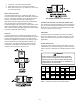
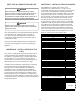
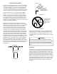

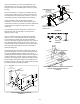


Table Of Contents
- Safety Considerations
- Electrostatic Discharge (ESD) Precautions
- To The Installer
- Product Application
- Location Requirements & Considerations
- Clearances and Accessibility
- Combustion & Ventilation Requirements
- Installation Positions
- Horizontal Applications & Considerations
- Vent Pipe & Combustion Air Pipe
- Materials – Installations In The U.S.A.
- Materials – Installations In Canada
- Pipe Installation
- Combustion Air Pipe Connection
- Vent/Intake Terminations For Installation of Multiple Direct Vent Furnaces
- Condensate Drain Lines & Drain Trap
- General Drain Information
- Field Supplied Drain
- Upflow Model Installed Vertically
- Drain Exiting Right Side
- Drain Exiting Left Side
- Upflow Model Installed Horizontally with Right Side Down
- Upflow Model Installed Horizontally with Left Side Down
- Upflow Model Installed Horizontally With Left Side Down - Alternate
- CounterFlow Model Installed Vertically
- Drain Exiting Left Side (See Figure 28)
- Drain Exiting Right Side (See Figure 29)
- Counterflow Model Installed Horizontally with Right Side Down (See Figure 30)
- Counterflow Model Installed Horizontally with Left Side Down (See Figure 31)
- Electrical Connections
- Gas Supply and Piping
- High Altitude Installation
- Circulating Air & Filters
- Filters - Read This Section Before Installing The Return Air Duct work
- Startup Procedure & Adjustment
- Gas Supply Pressure Measurement
- Operational Checks
- Safety Circuit Description
- Maintenance
- Filters
- Before Leaving an Installation
- Repair and Replacement Parts
- Special Instructions for Products Installed in the State of Massachusetts

17
1. Remove the four screws from the vent pipe ange
on top the furnace.
2. Remove the internal elbow, vent pipe & gasket.
3. Cut the internal vent pipe 2 1/2” from the ange.
Discard the un-anged section.
4. Remove the 3” plastic plug (in line with the inducer
outlet) and insert it in the space vacated by removal
of the internal vent pipe.
5. Install the RF000142 drain coupling with arrow
facing up, on the draft inducer outlet.
6. Insert the 2 ½” anged section of pipe with gasket
through the 3” hole and connect to RF000142 drain
coupling. Secure it with gear clamp provided.
7. Use the four self-tapping screws removed in step 1
to secure ange to cabinet.
8. Connect drain hose to the uncapped port on the
RF000142 coupling, refer to page xx, section
entitled “Horizontal Installation with Left Side Down
– Alternate” for drain connection details
When using the alternate venting location, either in
a horizontal left side down installation or a vertical
installation using down – venting, the alternate combustion
air opening can be used. A locating dimple is located on
the right side of the furnace cabinet. The locating dimple is
1-7/8” measured from the front edge of the cabinet in line
with the knock out.
To use the alternate combustion air location:
1. Remove screws and combustion air ange and
gasket from cabinet.
2. Insert the 3” cabinet plug from the drain bag
assembly in the unused combustion air hole.
3. Drill a pilot hole at the cabinet dimple (size dictated
by knockout tool used).
4. Use a knockout tool to create a 3” diameter hole.
5. Secure the combustion air ange & gasket to the
furnace cabinet using the self-tapping screws
removed in step 1.
T
HE
RUBBER
ELBOW
IS
NOT
DESIGNED
TO
SUPPORT
A
LOAD
. W
HEN
THE
RUBBER
ELBOW
IS
MOUNTED
EXTERNALLY
TO
THE
FURNACE
CABINET
,
EXTREME
CARE
MUST
BE
TAKEN
TO
ADEQUATELY
SUPPORT
FIELD
-
SUPPLIED
VENT
/
FLUE
PIPING
,
AS
DAMAGE
CAN
RESULT
IN
LEAKS
CAUSING
BODILY
INJURY
OR
DEATH
DUE
TO
EXPOSURE
TO
FLUE
GASES
,
INCLUDING
CARBON
MONOXIDE
B
E
SURE
NOT
TO
DAMAGE
INTERNAL
WIRING
OR
OTHER
COMPONENTS
WHEN
REINSTALLING
COUPLING
AND
SCREWS
.
Vent Pipe
Use alternate vent
& combination
air locations
Combustion Air Pipe
Field Supplied
Drain Tee on Vent Pipe
Condensate trapped
to prevent flue gas from escaping
and routed to field supplied
condensate disposal
1/4” per foot min.
slope to furnace
6’ Max.
Floor
B
a
s
e
m
e
n
t
/
C
r
a
w
l
s
p
a
c
e
DOWN VENTING UPFLOW MODEL FURNACES ONLY
All piping and fittings must be joined per material manufacturers specifications
to prevent separation and flue gas leaks.
Products of combustion must always be vented outside. A
vent pipe must never terminate in an attic, crawl space, or
any other part of a dwelling. Follow the vent pipe & intake
pipe termination requirements listed below as well as all
applicable local, State and National codes.
All terminations (vent and/or intake) must be located at
least 12” above ground level or the anticipated snow level.
All vent terminations (non-direct and direct vent) must
terminate at least 3 feet above any forced air inlet located
within 10 feet.
The vent termination of a non-direct vent application must
terminate at least 4 feet below, 4 feet horizontally from, or
1 foot above any door, window, or gravity air inlet into any
building.