
GC9S96 Installation Manual
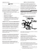
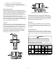
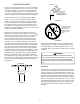
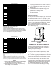
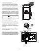

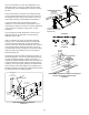


Table Of Contents
- Safety Considerations
- Electrostatic Discharge (ESD) Precautions
- To The Installer
- Product Application
- Location Requirements & Considerations
- Clearances and Accessibility
- Combustion & Ventilation Requirements
- Installation Positions
- Horizontal Applications & Considerations
- Vent Pipe & Combustion Air Pipe
- Materials – Installations In The U.S.A.
- Materials – Installations In Canada
- Pipe Installation
- Combustion Air Pipe Connection
- Vent/Intake Terminations For Installation of Multiple Direct Vent Furnaces
- Condensate Drain Lines & Drain Trap
- General Drain Information
- Field Supplied Drain
- Upflow Model Installed Vertically
- Drain Exiting Right Side
- Drain Exiting Left Side
- Upflow Model Installed Horizontally with Right Side Down
- Upflow Model Installed Horizontally with Left Side Down
- Upflow Model Installed Horizontally With Left Side Down - Alternate
- CounterFlow Model Installed Vertically
- Drain Exiting Left Side (See Figure 28)
- Drain Exiting Right Side (See Figure 29)
- Counterflow Model Installed Horizontally with Right Side Down (See Figure 30)
- Counterflow Model Installed Horizontally with Left Side Down (See Figure 31)
- Electrical Connections
- Gas Supply and Piping
- High Altitude Installation
- Circulating Air & Filters
- Filters - Read This Section Before Installing The Return Air Duct work
- Startup Procedure & Adjustment
- Gas Supply Pressure Measurement
- Operational Checks
- Safety Circuit Description
- Maintenance
- Filters
- Before Leaving an Installation
- Repair and Replacement Parts
- Special Instructions for Products Installed in the State of Massachusetts

19
Center to center = 10” min / 24” max.
Vertical separation: 0” - 24”
Vent termination from wall = 8” min / 12” max.
Combustion air intake from wall = 6” max.
Vent and intake clearance to ground or anticipated snow
level = 12” min.
3” MIN
12” MIN TO GRADE OR HIGHEST
ANTICIPATED SNOW LEVEL
3”MIN
24”MAX
12” M IN SE PARATION
If more than one direct vent furnace is to be installed
vertically through a common roof top, maintain the same
minimum clearances between the exhaust vent and air
intake terminations of adjacent units as with the exhaust
vent and air intake terminations of a single unit.
If more than one direct vent furnace is to be installed
horizontally through a common side wall, maintain the
clearances as in the Figure 20. Always terminate all
exhaust vent outlets at the same elevation and always
terminate all air intakes at the same elevation.
Vertical Installation
Horizontal Installation
Refer to the directions provided with the Concentric Vent Kit or
IO-619 for installation specications.
ELBOW
ELBOWS
ELBOWS
3”-24” BETWEEN PIPES