
GC9S96 Installation Manual
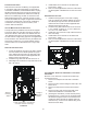
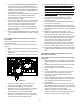
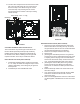
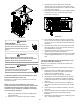

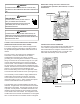
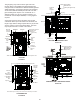
Table Of Contents
- Safety Considerations
- Electrostatic Discharge (ESD) Precautions
- To The Installer
- Product Application
- Location Requirements & Considerations
- Clearances and Accessibility
- Combustion & Ventilation Requirements
- Installation Positions
- Horizontal Applications & Considerations
- Vent Pipe & Combustion Air Pipe
- Materials – Installations In The U.S.A.
- Materials – Installations In Canada
- Pipe Installation
- Combustion Air Pipe Connection
- Vent/Intake Terminations For Installation of Multiple Direct Vent Furnaces
- Condensate Drain Lines & Drain Trap
- General Drain Information
- Field Supplied Drain
- Upflow Model Installed Vertically
- Drain Exiting Right Side
- Drain Exiting Left Side
- Upflow Model Installed Horizontally with Right Side Down
- Upflow Model Installed Horizontally with Left Side Down
- Upflow Model Installed Horizontally With Left Side Down - Alternate
- CounterFlow Model Installed Vertically
- Drain Exiting Left Side (See Figure 28)
- Drain Exiting Right Side (See Figure 29)
- Counterflow Model Installed Horizontally with Right Side Down (See Figure 30)
- Counterflow Model Installed Horizontally with Left Side Down (See Figure 31)
- Electrical Connections
- Gas Supply and Piping
- High Altitude Installation
- Circulating Air & Filters
- Filters - Read This Section Before Installing The Return Air Duct work
- Startup Procedure & Adjustment
- Gas Supply Pressure Measurement
- Operational Checks
- Safety Circuit Description
- Maintenance
- Filters
- Before Leaving an Installation
- Repair and Replacement Parts
- Special Instructions for Products Installed in the State of Massachusetts

23
10. Use two silver clamps and secure the hoses to drain
trap. The trap outlet faces the front of the furnace.
Secure the trap to the cabinet using two screws
removed in step 2 by inserting the two screws
through the large set of holes in the top mounting
tabs of the trap.
R 000142
F
The furnace drain may exit the right or left side of the
furnace cabinet (left side preferred) Trap and factory
installed hoses remain as shipped if the drain will exit
the left side of the cabinet. Draining from the right side
requires relocation of the trap to outside the cabinet.
1. Install a eld supplied rubber coupling secured with
a 1 1/4” clamp to enable removing the trap for future
cleaning. Alternately, a PVC tting may be glued on
the trap outlet.
2. Install drain per local and National codes.
Hose #4 x 3
Hose #5
1. Removing the gas manifold assembly will provide
better access when re-locating the trap. To remove
the gas manifold, remove the four screws that fasten
the gas manifold assembly to the bracket.
2. Remove hose clamps and hoses from trap.
3. Remove trap.
4. (Draining the Vent Elbow) Insert the non-grommet
end hose #10 into the cabinet back drain hole. Insert
a coupling into the drip leg of the vent-drain elbow
and secure with a silver clamp. Secure hose #10 on
vent - drain elbow barb tting with a silver clamp.
5. (Draining the Collector Box) Insert non-grommet
end of hose #9 into the cabinet front drain hole
and secure on collector box drain port with a silver
clamp.
6. Mate the drain trap inlets to the hoses and secure
with silver clamps.
7. Line up the trap mounting holes with the pre-drilled
holes in the furnace and secure with 2 screws
removed in step 2.
8. Refer to Field Supplied Drain section for instructions
on eld supplied / installed drain on outlet of furnace
trap.