
GC9S96 Installation Manual
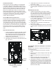
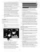
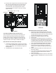
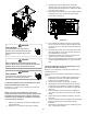

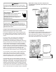
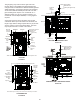
Table Of Contents
- Safety Considerations
- Electrostatic Discharge (ESD) Precautions
- To The Installer
- Product Application
- Location Requirements & Considerations
- Clearances and Accessibility
- Combustion & Ventilation Requirements
- Installation Positions
- Horizontal Applications & Considerations
- Vent Pipe & Combustion Air Pipe
- Materials – Installations In The U.S.A.
- Materials – Installations In Canada
- Pipe Installation
- Combustion Air Pipe Connection
- Vent/Intake Terminations For Installation of Multiple Direct Vent Furnaces
- Condensate Drain Lines & Drain Trap
- General Drain Information
- Field Supplied Drain
- Upflow Model Installed Vertically
- Drain Exiting Right Side
- Drain Exiting Left Side
- Upflow Model Installed Horizontally with Right Side Down
- Upflow Model Installed Horizontally with Left Side Down
- Upflow Model Installed Horizontally With Left Side Down - Alternate
- CounterFlow Model Installed Vertically
- Drain Exiting Left Side (See Figure 28)
- Drain Exiting Right Side (See Figure 29)
- Counterflow Model Installed Horizontally with Right Side Down (See Figure 30)
- Counterflow Model Installed Horizontally with Left Side Down (See Figure 31)
- Electrical Connections
- Gas Supply and Piping
- High Altitude Installation
- Circulating Air & Filters
- Filters - Read This Section Before Installing The Return Air Duct work
- Startup Procedure & Adjustment
- Gas Supply Pressure Measurement
- Operational Checks
- Safety Circuit Description
- Maintenance
- Filters
- Before Leaving an Installation
- Repair and Replacement Parts
- Special Instructions for Products Installed in the State of Massachusetts

25
8.
Insert rubber plug removed in step 7 into the 100°
elbow. (Inserting a blunt tool such as a 3/16’’ Allen
wrench into the center of the rubber plug will stretch
the plug and allow complete insertion)
Hose #4
Hose #5
Hose #4
Hose #2
9. Place radius end of hose #4 on the side port of vent
– drain elbow and secure with a gold clamp.
10. Insert a ½” diameter PVC pipe (factory installed) into
hose #4 and secure with a gold clamp.
11. Insert the non-grommet end of hose #5 (factory
installed) from outside the cabinet in the back drain
hole.
12. Insert 100º elbow in hose #5 and secure with a red
clamp.
13. Locate hose #4 and cut a cut o a 4” straight section
and discard the radius end.
14. Connect the 4” straight section of hose #4 to the
100º elbow and the PVC pipe and secure with red
clamps.
15. Connect the hoses to the trap inlets and secure
with silver clamps, drain trap outlet must point to the
original bottom of the furnace.
16. Using the two sheet metal screws provided in the
cabinet, secure the trap to the furnace.
17. Refer to Field Supplied Drain section for instructions
on eld supplied / installed drain on outlet of furnace
trap.
The wiring harness is an integral part of this furnace.
Wires are color coded for identication purposes. Refer to
the wiring diagram for wire routings. If any of the original
wire as supplied with the furnace must be replaced, it must
be replaced with wiring material having a temperature
rating of at least 105° C. Any replacement wiring must be
a copper conductor.
Before proceeding with electrical connections, ensure that
the supply voltage, frequency, and phase correspond to
that specied on the unit rating plate. Power supply to
the furnace must be NEC Class 1, and must comply with
all applicable codes. The furnace must be electrically
grounded in accordance with local codes or, in their
absence, with the latest edition of The National Electric
Code, ANSI NFPA 70 and/or The Canadian Electric Code
CSA C22.1.
HIGH VOLTAGE !
T
O
AVOID
PERSONAL
INJURY
OR
DEATH
DUE
TO
ELECTRICAL
SHOCK
,
DISCONNECT
ELECTRICAL
POWER
BEFORE
SERVICING
OR
CHANGING
ANY
ELECTRICAL
WIRING
.
Humidifier 1.0 Amp maximum at 120 VAC
Electronic Air Cleaner 1.0 Amp maximum at 120 VAC
Use a separate fused branch electrical circuit containing
properly sized wire, and fuse or circuit breaker. The fuse
or circuit breaker must be sized in accordance with the
maximum overcurrent protection specied on the unit
rating plate. An electrical disconnect must be provided at
the furnace location.
Connect hot, neutral, and ground wires as shown in the
wiring diagram located on the unit’s blower door. Metal
conduit is not considered a substitute for an actual ground
wire to the unit. For direct vent applications, the cabinet
opening to the junction box must be sealed air tight using
either an UL approved bushing such as Heyco Liquid
Tight or by applying non-reactive UL approved sealant to
bushing.
Line polarity must be observed when making eld
connections. Line voltage connections can be made
through either the right or left side panel. The furnace
is shipped congured for a left side (right side for
counterows) electrical connection with the junction box
located inside the burner compartment. To make electrical
connections through the opposite side of the furnace, the
junction box must be relocated to the other side of the
burner compartment prior to making electrical connections.
To relocate the junction box, follow the steps shown in the
Junction Box Relocation section.
E
DGES
OF
SHEET
METAL
HOLES
MAY
BE
SHARP
. U
SE
GLOVES
AS
A
PRECAUTION
WHEN
REMOVING
HOLE
PLUGS
.