
GC9S96 Installation Manual


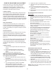


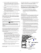


Table Of Contents
- Safety Considerations
- Electrostatic Discharge (ESD) Precautions
- To The Installer
- Product Application
- Location Requirements & Considerations
- Clearances and Accessibility
- Combustion & Ventilation Requirements
- Installation Positions
- Horizontal Applications & Considerations
- Vent Pipe & Combustion Air Pipe
- Materials – Installations In The U.S.A.
- Materials – Installations In Canada
- Pipe Installation
- Combustion Air Pipe Connection
- Vent/Intake Terminations For Installation of Multiple Direct Vent Furnaces
- Condensate Drain Lines & Drain Trap
- General Drain Information
- Field Supplied Drain
- Upflow Model Installed Vertically
- Drain Exiting Right Side
- Drain Exiting Left Side
- Upflow Model Installed Horizontally with Right Side Down
- Upflow Model Installed Horizontally with Left Side Down
- Upflow Model Installed Horizontally With Left Side Down - Alternate
- CounterFlow Model Installed Vertically
- Drain Exiting Left Side (See Figure 28)
- Drain Exiting Right Side (See Figure 29)
- Counterflow Model Installed Horizontally with Right Side Down (See Figure 30)
- Counterflow Model Installed Horizontally with Left Side Down (See Figure 31)
- Electrical Connections
- Gas Supply and Piping
- High Altitude Installation
- Circulating Air & Filters
- Filters - Read This Section Before Installing The Return Air Duct work
- Startup Procedure & Adjustment
- Gas Supply Pressure Measurement
- Operational Checks
- Safety Circuit Description
- Maintenance
- Filters
- Before Leaving an Installation
- Repair and Replacement Parts
- Special Instructions for Products Installed in the State of Massachusetts

32
Install the duct system in accordance with Standards of
the National Board of Fire Underwriters for the Installation
of Air Conditioning, Warm Air Heating and Ventilating
Systems. Pamphlets No. 90A and 90B.
A closed return duct system must be used, with the return
duct connected to the furnace. NOTE: Ductwork must
never be attached to the back of the furnace. For upow
installations requiring 1800 CFM or more, use either two
side returns or bottom return or a combination of side /
bottom. Flexible joints may be used for supply and return
con nections to reduce noise transmission. To prevent the
blower from inter fering with combustion air or draft when a
central return is used, a connecting duct must be installed
between the unit and the utility room wall. Never use a
room, closet, or alcove as a return air chamber.
Refer to your furnace rating plate for the maximum ESP
(external duct static) rating.
Total external static refers to everything external to the
furnace cabinet. Cooling coils, lters, ducts, grilles,
registers must all be considered when reading your total
external static pressure. The supply duct pressure must
be read between the furnace and the cooling coil. This
reading is usually taken by removing the “A” shaped block
o plate from the end on the coil; drilling a test hole in
it and reinstalling the block o plate. Take a duct static
reading at the test hole. Tape up the test hole after your
test is complete. The negative pressure must be read
between the lter and the furnace blower.
Too much external static pressure will result in insucient
air that can cause excessive temperature rise. This can
cause limit switch tripping and heat exchanger failure.
To determine total external duct static pressure, proceed
as follows;
1. With clean lters in the furnace, use a manometer to
measure the static pressure of the return duct at the
inlet of the furnace. (Negative Pressure)
2. Measure the static pressure of the supply duct.
(Positive Pressure)
3. The dierence between the two numbers is .4” w.c.
Example:
-1
0
1 2
3
Difference is 4
Static reading from return duct = -.1” w.c.
Static reading from supply duct = .3” w.c.
Total external static pressure on this system = .4” w.c.
air conditioner coil or Electronic Air Cleaner is used in
4. Consult proper tables for the quantity of air.
If the total external static pressure exceeds the maximum
listed on the furnace rating plate, check for closed
dampers, registers, undersized and/or oversized poorly
laid out duct work.
The temperature rise of the furnace must be within the
temperature rise range listed on the furnace rating plate.
Digital
Manometer
E
DGES
OF
SHEET
METAL
HOLES
MAY
BE
SHARP
. U
SE
GLOVES
AS
A
PRECAUTION
WHEN
REMOVING
SHEET
METAL
FROM
RETURN
AIR
OPENINGS
.
The bottom return air opening on upow models utilizes
a “lance and cut” method to remove sheet metal from the
duct opening in the base pan. To remove, simply press
out the lanced sections by hand to expose the metal strips
retaining the sheet metal over the duct opening. Using
tin snips, cut the metal strips and remove the sheet metal
covering the duct opening. In the corners of the opening,
cut the sheet metal along the scribe lines to free the duct
anges. Using the scribe line along the duct ange as a
guide, unfold the duct anges around the perimeter of the
opening using a pair of seamer pliers or seamer tongs.
performance issues and noise issues.