
GC9S96 Installation Manual
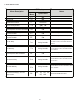
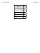

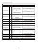
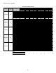

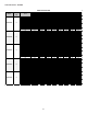

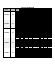
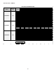
Table Of Contents
- Safety Considerations
- Electrostatic Discharge (ESD) Precautions
- To The Installer
- Product Application
- Location Requirements & Considerations
- Clearances and Accessibility
- Combustion & Ventilation Requirements
- Installation Positions
- Horizontal Applications & Considerations
- Vent Pipe & Combustion Air Pipe
- Materials – Installations In The U.S.A.
- Materials – Installations In Canada
- Pipe Installation
- Combustion Air Pipe Connection
- Vent/Intake Terminations For Installation of Multiple Direct Vent Furnaces
- Condensate Drain Lines & Drain Trap
- General Drain Information
- Field Supplied Drain
- Upflow Model Installed Vertically
- Drain Exiting Right Side
- Drain Exiting Left Side
- Upflow Model Installed Horizontally with Right Side Down
- Upflow Model Installed Horizontally with Left Side Down
- Upflow Model Installed Horizontally With Left Side Down - Alternate
- CounterFlow Model Installed Vertically
- Drain Exiting Left Side (See Figure 28)
- Drain Exiting Right Side (See Figure 29)
- Counterflow Model Installed Horizontally with Right Side Down (See Figure 30)
- Counterflow Model Installed Horizontally with Left Side Down (See Figure 31)
- Electrical Connections
- Gas Supply and Piping
- High Altitude Installation
- Circulating Air & Filters
- Filters - Read This Section Before Installing The Return Air Duct work
- Startup Procedure & Adjustment
- Gas Supply Pressure Measurement
- Operational Checks
- Safety Circuit Description
- Maintenance
- Filters
- Before Leaving an Installation
- Repair and Replacement Parts
- Special Instructions for Products Installed in the State of Massachusetts

44
Symptom
LED
Status
Fault Description Corrective Actions
Flame sense micro amp signal is minimal
Flame sensor is coated/oxidized
Flame sensor incorrectly positioned in burner
fame
Compare current gas pressure to rating plate and adjust
as needed
Problem with igniter circuit
Check and correct wiring from integrated control module to
igniter
Improperly connected or shorted igniter
Poor unit ground
Igniter relay fault on integrated control module
Check igniter output from control, replace if necessary
Polarity of 115 volt AC is reversed Correct polarity, check and correct wiring if necessary
Poor unit ground Verify proper ground, correct if necessary
Gas valve is not energized when it should be Check wiring in gas valve circuit
External Gas Valve Error Replace integrated control board
Gas valve is energized when it should not be Check wiring in gas valve circuit
Internal gas valve error Replace integrated
control board
Furnace fails to operate.
No 115 power to furnace or no 24 volt power
to integrated control module.
Restore high voltage power to furnace and integrated
control module.
Blown fuse or tripped circuit breaker
Correct condition which caused fuse to open, replace fuse
Integrated control module is non- functional
Replace non-functional integrated control module.
Furnace fails to operate
Grounding fault
Poor neutral connection
Verify neutral wire connection to furnace & continuity to
ground source
Furnace fails to operate Open roll out switch
Check for correct gas pressure Check for correct burner
alignment
Check for and correct burner restriction
Furnace fails to operate Ignitor Open
Check for Ignitor wiring.
Replace Damaged Ignitor
Furnace fails to operate
Inducer relay Error Replace integrated control board
Twinning feature not working TWIN Error
Check for wiring connections.
Replace integrated control board
Furnace fails to operate Internal Faults or IRQ Loss in Control Board Replace integrated control board
TROUBLESHOOTING CHART
Furnace fails to operate
Diagnose and replace shorted igniter as needed Verify and
correct unit ground wiring if needed
Normal furnace operation
Clean flame sensor if coated or oxidized Inspect for proper
flame sensor alignment
Lazy burner flame due to improper gas
pressure or combustion air
Furnace fails to operate
None
Integrated control module
LED display provides no
signal
Furnace fails to operate
Furnace fails to operate