Service and Troubleshooting GM9S92 / GM9S96 / GC9S96 / AM9S92 / AM9S96 / AC9S96 / VM9S96 / VC9S96 Single Stage Gas Furnaces and Accessories Pride and workmanship go into every product to provide our customers with quality products. It is possible, however, that during its lifetime a product may require service.
IMPORTANT INFORMATION IMPORTANT NOTICES RECOGNIZE SAFETY SYMBOLS, WORDS AND LABELS Pride and workmanship go into every product to provide our customers with quality products. It is possible, however, that during its lifetime a product may require service. Products should be serviced only by a qualified service technician who is familiar with the safety procedures required in the repair and who is equipped with the proper tools, parts, testing instruments and the appropriate service manual.
IMPORTANT INFORMATION WARNING If the information in these instructions is not followed exactly, a fire or explosion may result causing property damage, personal injury or loss of life. - do not store or use gasoline or other flammable vapors and liquids in the vicinity of this or any other appliance. - WHAT TO DO IF YOU SMELL GAS: • Do not try to light any appliance. • Do not touch any electrical switch; do not use any phone in your building. • Immediately call your gas supplier from a neighbor’s phone.
NOMENCLATURE PRODUCT IDENTIFICATION The model and manufacturing number are used for positive identification of component parts used in manufacturing. Please use these numbers when requesting service or parts information. G 1 Brand G - Goodman® Brand V - GMC® Brand A- AMANA® Brand Configuration M - Upflow/Horizontal C - Downflow/Horizontal 9 5 6 6 0 7 6 8 0 9 3 10 B 11 N 12 A 13 A 14 Nox N = > 40 NG/J NOx X = < 40 NG/J NOx U = < 14NG/J NOx Cabinet Width A - 14" B - 17.5" C - 21" D - 24.
SYSTEM OPERATION Safety Please adhere to the following warnings and cautions when installing, adjusting, altering, servicing, or operating the furnace. WARNING To prevent personal injury or death due to improper installation, adjustment, alteration, service, or maintenance, refer to this manual. For additional assistance or information, consult a qualified installer, servicer, agency or the gas supplier.
SYSTEM OPERATION A copy of the National Fuel Gas Code (NFPA 54/ANSI Z223.
SYSTEM OPERATION • • • • Isolate a nondirect furnace from an area contaminated by any of the above substances. This protects the nondirect vent furnace from airborne contaminants. To ensure that the enclosed non-direct vent furnace has an adequate supply of combustion air, vent from a nearby uncontaminated room or from outdoors. Refer to the Combustion and Ventilation Air Requirements section in this manual or the installation instructions for details.
SYSTEM OPERATION e. Test for draft hood equipped spillage at the draft hood relief opening after 5 minutes of main burner operation. Use the flame of a match or candle. f. After it has been determined that each appliance connected to the venting system properly vents when tested as outlined above, return doors, windows, exhaust fans, fireplace dampers and any other gas burning appliance to their previous conditions of use. g.
SYSTEM OPERATION 9.3.2.1* Standard Method. The minimum required volume shall be 50 ft 3 per 1,000/Btu/hour (4.8m3/kW). 9.3.2.2* Known Air Infiltration Rate Method.
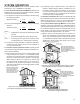
SYSTEM OPERATION (2)*Where communicating with the outdoors through horizontal ducts, each opening shall have a minimum free area of 1 in.2/2000 Btu/hr (1100 min2/kW) of total input rating of all appliances in the enclosure. [See Figure A.9.3.3.1(2).] Chimney or Gas Vent NOTE: The air duct openings must have a free area of not less than one square inch per 2000 BTU of the total input rating of all equipment in the enclosure*. Outlet air duct Furnace Water Heater 9.3.5 Engineered Installations.
SYSTEM OPERATION 9.3.8.1 Ducts shall be constructed of galvanized steel or a material having equivalent corrosion resistance, strength, and rigidity. Exception: Within dwellings units, unobstructed stud and joist spaces shall not be prohibited from conveying combustion air, provided that not more than one fireblock is removed. 9.3.8.2 Ducts shall terminate in an unobstructed space, allowing free movement of combustion air to the appliances. 9.3.8.3 Ducts shall serve a single space. 9.3.8.
SYSTEM OPERATION Propane Gas and/or High Altitude Installations AIR DISCHARGE WARNING Side Return Duct Connection Possible property damage, personal injury or death may occur if the correct conversion kits are not installed. The appropriate kits must be applied to ensure safe and proper furnace operation. All conversions must be performed by a qualified installer or service agency.
SYSTEM OPERATION It is the responsibility of the installer to follow the manufacturers’ recommendations and to verify that all vent/flue piping and connectors are compatible with furnace flue products. Additionally, it is the responsibility of the installer to ensure that all piping and connections possess adequate structural integrity and support to prevent flue pipe separation, shifting, or sagging during furnace operation.
SYSTEM OPERATION *M9S9 / *C9S9 Direct Vent (2-Pipe) & Non-Direct Vent (1-Pipe) (6) Maximum Allowable Length of Vent/Flue Pipe Number of Elbow s (3) MODEL *M9S920403AN *M9S920603BN *M9S920803BN *M9S920804CN *M9S920805CN *M9S921004CN *M9S921005CN *M9S921205DN MODEL *M9S960403AN *M9S960603BN *M9S960803BN *M9S960804BN *M9S960805CN *M9S961005CN *M9S961205DN *C9S960403BN *C9S960603BN *C9S960804CN *C9S961005CN *C9S961205DN PIPE (5) 1 2 3 4 5 6 7 8 2^ 108 105 101 97 93 90 86 82 3 126 120 1
SYSTEM OPERATION 12" MIN. 90° ELBOWS VENT/FLUE TEE (OPTIONAL) or 45° ELBOW TURNED DOWN or 90° ELBOW TURNED DOWN 3”-24” BETWEEN PIPES 12" MIN. ABOVE HIGHEST ANTICIPATED SNOW LEVEL Horizontal Termination (Single Pipe) Above Highest Anticipated Snow Level 12" MIN. ABOVE HIGHEST ANTICIPATED SNOW LEVEL Combustion Air Intake may also be snorkeled to obtain 12” min ground clearance.
SYSTEM OPERATION Concentric Vent Kits Application The Concentric Vent Kits are designed to allow the terminations of a direct vent furnace to be “concentrically” vented through a wall or roof. This kit allows a single penetration to support terminations for both the vent/flue pipe and the combustion air intake pipe. Vent Termination Clearances 1. Determine termination locations based on clearances specified in furnace installation instructions, and following steps as shown in Figures 1, 3, 6, 7, 8 and 9.
SYSTEM OPERATION Option 2 The internal vent pipe and elbow may be removed from the furnace to permit the vent to exit the top (original side) of the furnace. If this option is used, an RF000142 Vent-Drain coupling must be used to keep condensate from collecting in the inducer assembly. To install the drain, refer to the following instructions and illustration.
SYSTEM OPERATION In some areas the gas supplier may artificially derate the gas in an effort to compensate for the effects of altitude. If the gas is artificially derated, the appropriate orifice size must be determined based upon the BTU/ft3 content of the derated gas and the altitude. Refer to the National Fuel Gas Code, NFPA 54/ANSI Z223.1, and information provided by the gas supplier to determine the proper orifice size.
SYSTEM OPERATION Gas Piping Connections WARNING To avoid possible unsatisfactory operation of equipment damage due to underfiring or equipment, use the proper size of natural/propane gas piping needed when running pipe from the meter/tank furnace. The gas piping supplying the furnace must be properly sized based on the gas flow required, specific gravity of the gas, and length of the run.
SYSTEM OPERATION 3. Pressure drop in lines between regulators, and between second stage regulator and the appliance. Pipe size will depend on length of pipe run and total load of all appliances. Complete information regarding tank sizing for vaporization, recommended regulator settings, and pipe sizing is available from most regulator manufacturers and propane gas suppliers. Use pipe dope approved for use with L.P. gas. Refer to the following illustration for typical propane gas installations and piping.
SYSTEM OPERATION When installing a propane storage tank, the contractor must consider proper tank sizing, safety, efficiency, ground characteristics and aesthetics. For a residential customer, the size may range from 100-1,000 gallons, depending on household use. Typically, a 500 gallon tank is ample for an average four-bedroom home. However, it is best to consult your local propane supplier to ensure the proper sizing for propane storage requirements.
SYSTEM OPERATION WARNING 115 VAC EAC 115 VAC HUM HIGH VOLTAGE! To avoid the risk of injury, electrical shock or death, the furnace must be electrically grounded in accordance with the local codes or in their absence, with the latest edition of the National Electrical Code. WARNING To avoid the risk of injury, electrical shock or death, the furnace must be electrically grounded in accordance with the local codes, or in their absence, with the latest edition of the National Electrical Code.
SYSTEM OPERATION 2. Remove and save the two screws securing the junction box to the side panel. 3. Relocate junction box and associated plugs and grommets to opposite side panel. Secure with screws removed in step. IMPORTANT NOTE: Wire routing must not interfere with circulator blower operation, filter removal or routine maintenance. To ensure proper unit grounding, the ground wire should run from the furnace ground screw located inside the furnace junction box all the way back to the electrical panel.
SYSTEM OPERATION FURNACE 2 W R G C Y/Y1 Y2 TWIN FURNACE 1 W R G C Y/Y1 Y2 TWIN ROOM THERMOSTAT W R G C Y/Y1 Y2 COND UNIT CONTACTOR COND UNIT CONTACTOR CAUTION To prevent unreliable operation or equipment damage, the gas manifold pressure must be as specified on the unit rating plate. Only minor adjustments should be made by adjusting the gas valve pressure regulator. WARNING Possible property damage, personal injury or death may occur if the correct conversion kits are not installed.
SYSTEM OPERATION • • • The gas valve is de-energized. The inducer remains energized for the post purge period (15 seconds). The indoor blower runs for the selected off delay period (90 seconds by default, adjustable from 30 – 180 seconds). Heating Mode Speed Selection To change the main blower speed in HEATING mode, follow the following steps: 1. Press left or right button till LED displays “gA1 “(for single stage HEATING).
SYSTEM OPERATION Cooling Mode Speed Selection To change the main blower speed in COOLING mode, follow the following steps: 1. Press the left or right switch until LED displays “AC1 “(for single stage COOLING) or “AC2 “(for two-stage COOLING). Press the center switch and LED will display the selected speed number as Fxx (xx: Blower speed number from 1 to 9). 2. The control will rotate available speed number every time left/right switches are pressed.
SCHEDULED MAINTENANCE WARNING HIGH VOLTAGE Disconnect ALL power before servicing or changing any electrical wiring. Multiple power sources may be present. Failure to do so may cause property damage, personal injury or death. MAINTENANCE Improper filter maintenance is the most common cause of inadequate heating or cooling performance. Filters should be cleaned (permanent) or replaced (disposable) every two months or as required. It is the owner’s responsibility to keep air filters clean.
SCHEDULED MAINTENANCE Proper equipment promotes faster, more efficient service and accurate repairs resulting in fewer call backs. HEATING PERFORMANCE TEST Before attempting to diagnose an operating fault code, run a Heating Performance Test to determine if the heating system is performing within 5% of the BTU input found on the rating plate of the unit being tested. To conduct a heating performance test, the BTU input to the unit must be calculated (see Clocking a Gas Meter).
SCHEDULED MAINTENANCE 4. Using Table 2 below, find the number of seconds it took for the dial to make a full revolution. To the right of that number of seconds and below the Size of Test Dial (selected in step 3 and shown in Table 1) will be the Cubic Feet per Hour (CFH).
SCHEDULED MAINTENANCE BTU/HR Calculation Example: The unit being tested takes 40 seconds for the 1 cubic foot dial to make one complete revolution. Using the chart, this translates to 90 cubic feet per hour. Based upon the assumption that one cubic foot of natural gas has 1,025 BTU’s (Check with your local utility for actual BTU content), the calculated input is 92,250 BTU’s per hour.
SCHEDULED MAINTENANCE *M9S92 Pressure Switch Trip Points And Usage Chart Model *M9S920403ANAA *M9S920603BNAA *M9S920803BNAA *M9S920804CNAA *M9S920805CNAA *M9S921004CNAA *M9S921005CNAA *M9S921205DNAA Coil Cover Set Point on Pressure Fall (PF) W.C. Coil Cover Max Make On Pressure Rise W.C. ID Blower Set Point on Pressure Fall (PF) W.C. ID Blower Max Make On Pressure Rise W.C. ID Blower Coil Cover Pressure Switch Assembly Part # - 0.10 ± .05 - 0.10 ± .05 - 0.10 ± .05 - 0.10 ± .05 - 0.10 ± .05 - 0.
SERVICING As more and more electronics are introduced to the Heating Trade, Polarization of incoming power and phasing of primary to secondary voltage on transformers becomes more important. INCOMING POWER 120.00 0.00 Polarization has been apparent in the Appliance industry since the introduction of the three prong plug, however, the Heating Industry does not use a plug for incoming power, but is hard wired. We recommend that these two items be checked during normal installation and/or service calls.
SERVICING CHECKING VOLTAGE WARNING HIGH VOLTAGE Disconnect ALL power before servicing or changing any electrical wiring. Multiple power sources may be present. Failure to do so may cause property damage, personal injury or death. 1. Remove the burner door on furnaces to gain entry to the Junction Box. 2. Remove cover from the Junction Box and gain access to incoming power lines. With Power ON: WARNING Line Voltage now present. 3.
SERVICING CHECKING TRANSFORMER AND CONTROL CIRCUIT A step-down transformer 120 volt primary to 24 volt secondary, 40 VA (Heating and Cooling Models) supplies ample capacity of power for either operation. WARNING HIGH VOLTAGE Disconnect ALL power before servicing or changing any electrical wiring. Multiple power sources may be present. Failure to do so may cause property damage, personal injury or death. 1.
SERVICING To determine proper air movement, proceed as follows: 1. With clean filters in the furnace, use a manometer to measure the static pressure of the return duct at the inlet of the furnace. (Negative Pressure) 2. Measure the static pressure of the supply duct. (Positive Pressure) 3. Add the two (2) readings together for total external static pressure. 2. Place thermometers in the return and supply ducts as close to the furnace as possible.
SERVICING The following drawing illustrates the style of limit switches used on the 90% furnaces. ENCLOSED DISK FRONT VIEW SIDE VIEW Primary Limit Control Style (90% Furnaces) WARNING HIGH VOLTAGE Disconnect ALL power before servicing or changing any electrical wiring. Multiple power sources may be present. Failure to do so may cause property damage, personal injury or death. 1. Remove burner compartment door to gain access to the primary limit. 2.
SERVICING WARNING Do not bypass any safety circuit. CHECKING FLAME ROLLOUT CONTROL A temperature activated manual reset control is mounted to the manifold assembly on 90% furnaces, as shown in the following illustrations. Measure the voltage between each side of the rollout control and ground while the ignition control tries to power the gas valve. 2. Measure the voltage between each side of the rollout control and ground during the ignition attempt. Refer to the following figure.
SERVICING 4. Touch one probe of the ohmmeter to the motor frame (ground) and the other probe in turn to each lead. If the windings do not test continuous or a reading is obtained to ground, replace the motor. 5. If the windings have a continuity reading, reconnect wires. Turn power on to the furnace and turn the thermostat on in the heating mode. Check voltage for 115V at the induced draft motor terminals during the trial for ignition.
SERVICING CHECKING GAS PRESSURE Gas Supply Pressure Measurement CAUTION To prevent unreliable operation or equipment damage, the inlet gas supply pressure must be as specified on the unit rating plate with all other household gas fired appliances operating. Gas inlet and manifold pressures should be checked and adjusted in accordance to the type of fuel being consumed. The line pressure supplied to the gas valve must be within the range specified below.
SERVICING WARNING HIGH VOLTAGE Disconnect ALL electrical power and shut off gas supply before servicing or installing. 1. After turning off gas to furnace at the manual gas shutoff valve external to the furnace, remove burner compartment door to gain access to the gas valve. 2. Connect a calibrated manometer (or appropriate gas pressure gauge) at the gas valve outlet pressure tap. Refer to Measuring Gas Pressure: Single Stage Valves figure for single stage valve outlet pressure tap connections.
SERVICING WARNING Manifold Gas Pressure Gas Propane Gas Rate Range Nominal High Stage 9.7 to 10.3" w.c. 10.0" w.c. Low Stage 5.7 to 6.3" w.c. 6.0" w.c. CHECKING HOT SURFACE IGNITOR Single stage furnaces use a 115 volt silicon carbide igniter (p/n 0130F00008) with 17-second warm up time. WARNING Disconnect ALL power before servicing. 1. Remove burner compartment door to gain access to the ignitor. 2. Ignitor cool - approximately 70 - 77°F. 3. Disconnect the ignitor from the Ignition Control. 4.
SERVICING 2. Improper burner positioning - burners should be in locating slots, level front to rear and left to right. 3. Carry over (lighter tube or cross lighter) obstructed clean. 4. Main burner orifice(s) deformed, or out of alignment to burner - replace.
SERVICING WARNING Line Voltage now present. 3. Place the unit into a heating cycle. 4. As soon as flame is established a micro-amp reading should be evident once proof of flame (micro-amp reading) is established, the hot surface ignitor will be de-energized. 5. The Integrated Ignition controls will have 1 to 4 micro-amps. If the micro-amp reading is less than the minimum specified, check for high resistance wiring connections, sensor to burner gap, dirty flame sensor, or poor grounding. 6.
1 STAGE STATUS CODES Menu Description Active Alaram menu Last 6 Faults Main Menu Option Menu xx xx Code Release Number CR Number Reset to Factory Default yes, no Blower Speed for Continous Fan Mode xx Blower Speed for 1st Stage Compressor Mode xx Blower Speed for 2nd Stage Compressor Mode xx Cool On Delay Blower Speed for Gas Heat Mode xx Automatic Heat Staging - For Two Stage Control ( xx: code numbers ) ( xx: Blower Speed Number F01,
1 STAGE STATUS CODES STATUS MENU Mode Idle Continous Fan Compressor Cooling, Low Stage Compressor Cooling, High Stage Gas heat - Single Stage Control OEM test Mode Main Menu 45
1 STAGE TROUBLESHOOTING CODES TROUBLESHOOTING CHART Symptom Normal operation LED Status Fault Description Corrective Actions Normal operation None Locate and correct gas interruption Replace or realign igniter Furnace fails to operate Furnace lockout due to an excessive number of ignition “retries” (3 total) Failure to establish flame Loss of flame after establishment Check flame sense signal, clean sensor if coated or oxidized Check flue piping for blockage, proper length, elbows, and ter
1 STAGE TROUBLESHOOTING CODES TROUBLESHOOTING CHART Symptom LED Status Fault Description Corrective Actions Flame sense micro amp signal is minimal Flame sensor is coated/oxidized Normal furnace operation Flame sensor incorrectly positioned in burner fame Lazy burner flame due to improper gas pressure or combustion air Problem with igniter circuit Furnace fails to operate Furnace fails to operate Furnace fails to operate Furnace fails to operate Furnace fails to operate.
AIRFLOW TABLES GC9S96 LOW STAGE COOLING AIFLOW MODEL THERMOSTAT CALL *C9S960403B* Y/Y1 *C9S960603B* Y/Y1 *C9S960804C* Y/Y1 *C9S961005C* Y/Y1 *C9S961205D* Y/Y1 TAP # 0.1 0.
AIRFLOW TABLES GC9S96 HIGH STAGE COOLING AIFLOW MODEL THERMOSTAT CALL *C9S960403B* Y2 *C9S960603B* Y2 *C9S960804C* Y2 *C9S961005C* Y2 *C9S961205D* Y2 TAP # F01 F02 F03 F04 F05^ F06 F07 F08 F09 F01 F02 F03 F04 F05^ F06 F07 F08 F09 F01 F02 F03 F04 F05^ F06 F07 F08 F09 F01 F02 F03 F04 F05^ F06 F07 F08 F09 F01 F02 F03 F04 F05^ F06 F07 F08 F09 0.
AIRFLOW TABLES GC9S96 CIRCULATION AIFLOW MODEL THERMOSTAT CALL *C9S960403B* G *C9S960603B* G *C9S960804C* G *C9S961005C* G *C9S961205D* G 50 TAP # F01 F02 F03 F04 F05 F06 F07 F08 F09 F01 F02 F03 F04 F05 F06 F07 F08 F09 F01 F02 F03 F04 F05 F06 F07 F08 F09 F01 F02 F03 F04 F05 F06 F07 F08 F09 F01 F02 F03 F04 F05 F06 F07 F08 F09 0.
AIRFLOW TABLES GC9S96 HEATING AIFLOW MODEL THERMOSTAT CALL *C9S960403B* W/W1 *C9S960603B* W/W1 *C9S960804C* W/W1 *C9S961005C* W/W1 *C9S961205D* W/W1 TAP # F01^^ F02^ F03 F04 F01^^ F02^ F03 F04 F01^^ F02^ F03 F04 F01^^ F02^ F03^^ F04 F01^^ F02^ F03 F04 CFM 632 727 878 948 771 1197 1309 1138 873 1442 1643 1600 1176 1773 1709 1651 1187 1973 1918 1835 0.
AIRFLOW TABLES GM9S92 LOW STAGE COOLING AIFLOW MODEL THERMOSTAT CALL *M9S920403A* Y/Y1 *M9S920603B* Y/Y1 *M9S920803B* Y/Y1 *M9S920804C* Y/Y1 *M9S920805C* Y/Y1 52 TAP # F01 F02 F03 F04^ F05 F06 F07 F08 F09 F01 F02 F03 F04^ F05 F06 F07 F08 F09 F01 F02 F03 F04^ F05 F06 F07 F08 F09 F01 F02 F03 F04^ F05 F06 F07 F08 F09 F01 F02 F03 F04^ F05 F06 F07 F08 F09 0.
AIRFLOW TABLES GM9S92 LOW STAGE COOLING AIFLOW MODEL THERMOSTAT CALL *M9S921004C* Y/Y1 *M9S921005C* Y/Y1 *M9S921205D* Y/Y1 TAP # F01 F02 F03 F04^ F05 F06 F07 F08 F09 F01 F02 F03 F04^ F05 F06 F07 F08 F09 F01 F02 F03 F04^ F05 F06 F07 F08 F09 0.1 CFM 809 1754 1648 1558 1303 1406 1445 1778 1824 906 1871 1831 1653 1496 1640 1955 2086 2222 1056 2096 2023 1946 1231 1503 1704 1831 2222 EXTERNAL STATIC PRESSURE, (INCHES WATER COLUMN) 0.2 0.3 0.4 0.5 0.6 0.
AIRFLOW TABLES MODEL THERMOSTAT CALL *M9S920403A* Y2 *M9S920603B* Y2 *M9S920803B* Y2 *M9S920804C* Y2 *M9S920805C* Y2 54 TAP # F01 F02 F03 F04 F05^ F06 F07 F08 F09 F01 F02 F03 F04 F05^ F06 F07 F08 F09 F01 F02 F03 F04 F05^ F06 F07 F08 F09 F01 F02 F03 F04 F05^ F06 F07 F08 F09 F01 F02 F03 F04 F05^ F06 F07 F08 F09 HIGH STAGE COOLING AIFLOW 0.
AIRFLOW TABLES MODEL THERMOSTAT CALL *M9S921004C* Y2 *M9S921005C* Y2 *M9S921205D* Y2 HIGH STAGE COOLING AIFLOW TAP # 0.1 CFM 809 1754 1648 1558 1303 1406 1445 1778 1824 906 1871 1831 1653 1496 1640 1955 2086 2222 1056 2096 2023 1946 1231 1503 1704 1831 2222 F01 F02 F03 F04 F05^ F06 F07 F08 F09 F01 F02 F03 F04 F05^ F06 F07 F08 F09 F01 F02 F03 F04 F05^ F06 F07 F08 F09 GM9S92 EXTERNAL STATIC PRESSURE, (INCHES WATER COLUMN) 0.2 0.3 0.4 0.5 0.6 0.
AIRFLOW TABLES GM9S92 CIRCULATION AIRFLOW MODEL THERMOSTAT CALL *M9S920403A* G *M9S920603B* G *M9S920803B* G *M9S920804C* G *M9S920805C* G 56 TAP # F01 F02 F03 F04 F05 F06 F07 F08 F09 F01 F02 F03 F04 F05 F06 F07 F08 F09 F01 F02 F03 F04 F05 F06 F07 F08 F09 F01 F02 F03 F04 F05 F06 F07 F08 F09 F01 F02 F03 F04 F05 F06 F07 F08 F09 0.
AIRFLOW TABLES GM9S92 CIRCULATION AIRFLOW MODEL THERMOSTAT CALL *M9S921004C* G *M9S921005C* G *M9S921205D* G TAP # F01 F02 F03 F04 F05 F06 F07 F08 F09 F01 F02 F03 F04 F05 F06 F07 F08 F09 F01 F02 F03 F04 F05 F06 F07 F08 F09 0.1 CFM 809 1754 1648 1558 1303 1406 1445 1778 1824 906 1871 1831 1653 1496 1640 1955 2086 2222 1056 2096 2023 1946 1231 1503 1704 1831 2222 EXTERNAL STATIC PRESSURE, (INCHES WATER COLUMN) 0.2 0.3 0.4 0.5 0.6 0.
AIRFLOW TABLES GM9S92 HEATING AIFLOW MODEL THERMOSTAT CALL *M9S920403A* W/W1 *M9S920603B* W/W1 *M9S920803B* W/W1 *M9S920804C* W/W1 *M9S920805C* W/W1 *M9S921004C* W/W1 *M9S921005C* W/W1 *M9S921205D* W/W1 0.
AIRFLOW TABLES GM9S96 LOW STAGE COOLING AIFLOW MODEL THERMOSTAT CALL *M9S960403A* Y/Y1 *M9S960603B* Y/Y1 *M9S960803B* Y/Y1 *M9S960804C* Y/Y1 TAP # F01 F02 F03 F04^ F05 F06 F07 F08 F09 F01 F02 F03 F04^ F05 F06 F07 F08 F09 F01 F02 F03 F04^ F05 F06 F07 F08 F09 F01 F02 F03 F04^ F05 F06 F07 F08 F09 0.
AIRFLOW TABLES MODEL THERMOSTAT CALL *M9S960805C* Y/Y1 *M9S961005C* Y/Y1 *M9S961205D* Y/Y1 TAP # F01 F02 F03 F04^ F05 F06 F07 F08 F09 F01 F02 F03 F04^ F05 F06 F07 F08 F09 F01 F02 F03 F04^ F05 F06 F07 F08 F09 LOW STAGE COOLING AIFLOW 0.1 CFM 1029 1814 1893 1738 1193 1421 1582 1962 2068 1008 2026 1921 1804 1475 1626 1693 1775 2161 1118 2143 2025 1906 1220 1684 1766 1863 2454 NOTE: ^ Default speed 60 GM9S96 EXTERNAL STATIC PRESSURE, (INCHES WATER COLUMN) 0.6 0.7 0.5 0.2 0.3 0.
AIRFLOW TABLES GM9S96 HIGH STAGE COOLING AIFLOW MODEL THERMOSTAT CALL *M9S960403A* Y2 *M9S960603B* Y2 *M9S960803B* Y2 *M9S960804C* Y2 TAP # F01 F02 F03 F04 F05^ F06 F07 F08 F09 F01 F02 F03 F04 F05^ F06 F07 F08 F09 F01 F02 F03 F04 F05^ F06 F07 F08 F09 F01 F02 F03 F04 F05^ F06 F07 F08 F09 0.
AIRFLOW TABLES GM9S96 HIGH STAGE COOLING AIFLOW MODEL THERMOSTAT CALL *M9S960805C* Y2 *M9S961005C* Y2 *M9S961205D* Y2 TAP # 0.1 CFM 1029 1814 1893 1738 1193 1421 1582 1962 2068 1008 2026 1921 1804 1475 1626 1693 1775 2161 1118 2143 2025 1906 1220 1684 1766 1863 2454 F01 F02 F03 F04 F05^ F06 F07 F08 F09 F01 F02 F03 F04 F05^ F06 F07 F08 F09 F01 F02 F03 F04 F05^ F06 F07 F08 F09 NOTE: ^ Default speed 62 EXTERNAL STATIC PRESSURE, (INCHES WATER COLUMN) 0.6 0.7 0.4 0.5 0.2 0.
AIRFLOW TABLES GM9S96 CIRCULATION AIRFLOW MODEL THERMOSTAT CALL *M9S960403A* G *M9S960603B* G *M9S960803B* G *M9S960804C* G TAP # F01 F02 F03 F04 F05 F06 F07 F08 F09 F01 F02 F03 F04 F05 F06 F07 F08 F09 F01 F02 F03 F04 F05 F06 F07 F08 F09 F01 F02 F03 F04 F05 F06 F07 F08 F09 0.
AIRFLOW TABLES GM9S96 CIRCULATION AIRFLOW MODEL THERMOSTAT CALL *M9S960805C* G *M9S961005C* G *M9S961205D* G 64 TAP # F01 F02 F03 F04 F05 F06 F07 F08 F09 F01 F02 F03 F04 F05 F06 F07 F08 F09 F01 F02 F03 F04 F05 F06 F07 F08 F09 0.1 CFM 1029 1814 1893 1738 1193 1421 1582 1962 2068 1008 2026 1921 1804 1475 1626 1693 1775 2161 1118 2143 2025 1906 1220 1684 1766 1863 2454 EXTERNAL STATIC PRESSURE, (INCHES WATER COLUMN) 0.2 0.3 0.4 0.5 0.6 0.
AIRFLOW TABLES GM9S96 HEATING AIFLOW MODEL THERMOSTAT CALL *M9S960403A* W/W1 *M9S960603B* W/W1 *M9S960803B* W/W1 *M9S960804C* W/W1 *M9S960805C* W/W1 *M9S961005C* W/W1 *M9S961205D* W/W1 TAP # F01^^ F02^ F03 F04 F01^^ F02^ F03 F04 F01^^ F02^ F03 F04 F01^^ F02^ F03 F04 F01^^ F02^ F03 F04 F01^^ F02^ F03 F04 F01^^ F02^ F03 F04^^ 0.1 CFM 705 1079 915 887 758 1218 1164 1121 715 1415 1388 1290 1019 1791 1625 1537 1029 1814 1893 1738 1008 2026 1921 1804 1118 2143 2025 1906 0.
WIRING DIAGRAMS *M9S92/*M9S96/*C9S96 GN GRD YL GY JUNCTION BOX ID BLOWER PRESSURE SWITCH HOT SURFACE IGNITER L YL DISCONNECT RD TO 115VAC/ 1Ø /60 HZ POWER SUPPLY WITH OVERCURRENT PROTECTION DEVICE C GY WH NO FLAME SENSOR SOME UNITS MAY HAVE 1 ROLL OUT SWITCH PU PU PK DISCONNECT JUNCTION BOX RD WH BK YL PK HUM-OUT IND BK WH BK FS FLAME SENSOR 115 VAC LINE EAC-H LINE-H CIRC-H XFMR-H NEUT2 NEUT1 HUM-N CIRC-N EAC-N XFMR-N LINE-N 2 1 RD 24 VAC YL T5 COM 3 2 5
CUSTOMER FEEDBACK We are very interested in all product comments. Please fill out the feedback form on one of the following links: Goodman® Brand Products: (http://www.goodmanmfg.com/about/contact-us). Amana® Brand Products: (http://www.amana-hac.com/about-us/contact-us). You can also scan the QR code on the right for the product brand you purchased to be directed to the feedback page.