
GC9S96 Service Manual


SYSTEM OPERATION
22
WARNING
WARNING
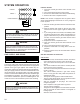
The furnace integrated control module is equipped with line
voltage accessory terminals for controlling power to an op-
Turn OFF power to the furnace before installing any acces-
-
structions for locating, mounting, grounding, and controlling
these accessories. Accessory wiring connections are to be
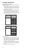
as 120V HUM-N. The electronic air cleaner hot terminal is
Connections should be made as shown. (See Figure 32)
If it is necessary for the installer to supply additional line
voltage wiring to the inside of the furnace, the wiring must
conform to all local codes, and have a minimum temperature
rating of 105°C. All line voltage wire splices must be made
inside the furnace junction box.
HUM-H is energized with 115 volts whenever the induced
draft blower is energized. This terminal can also be used to
-
maining primary transformer wire would be connected to the
Line N on the control board. The integrated control module
electronic air cleaner terminals EAC-H is energized with 115
volts whenever the circulator blower is energized.
Wire routing must not to interfere with circulator
115 VAC EAC
115 VAC HUM
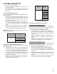
W R G C Y
V HUM” is energized with 24 volts whenever the induced
draft blower is energized. Connect the common side of the
-
nal strip on the control board.
24 VOLT HUM. &
HUMIDISTAT
W R G C Y
24V HUM Terminal is
energized when pressure
switch is closed
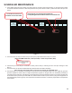
Line voltage connections can be made through either the
a left side electrical connection. To make electrical connec-
tions through the opposite side of the furnace, the junction
box must be relocated to the left side prior to making elec-
trical connections. To relocate the junction box, perform the
following steps.
1. Remove the burner compartment door.