
GC9S96 Service Manual


SYSTEM OPERATION
7
• Isolate a nondirect furnace from an area contaminated
by any of the above substances. This protects the non-
direct vent furnace from airborne contaminants. To
ensure that the enclosed non-direct vent furnace has an
adequate supply of combustion air, vent from a nearby
uncontaminated room or from outdoors. Refer to the
Combustion and Ventilation Air Requirements section
in this manual or the installation instructions for details.
• If the furnace is used in connection with a cooling unit,
install the furnace upstream or in parallel with the cooling
unit coil. Premature heat exchanger failure will result if
the cooling unit coil is placed ahead of the furnace.
• If the furnace is installed in a residential garage, position
the furnace so that the burners and ignition source are
Protect the furnace from physical damage by vehicles.
• If the furnace is installed horizontally, the furnace
horizontally into the heat exchanger. Do not install the
unit with the access doors on the “up/top” or “down/
bottom” side of the furnace.
Installations must adhere to the clearances to combustible
minimum clearance information for this furnace is provided on
the unit’s clearance label. These clearances must be perma-
clearances to combustible materials. Clearances must also
accommodate an installation’s gas, electrical, and drain trap
and drain line connections. If the alternate combustion air in-
-
ditional clearances must be provided to accommodate these
connections. Refer to Vent Flue Pipe and Combustion Air
Pipe section in this manual or the installation instructions for
details. In addition to the required clearances to com-
bustible materials, a minimum of 24 inches service clearance
must be available in front of the unit.
room) must have two ventilation openings with a total min-
imum free area of 0.25 square inches per 1,000 BTU/hr of
furnace input rating. One of the ventilation openings must be
within 12 inches of the top; the other opening must be within
construction, the clearance between the door and door frame
is usually adequate to satisfy this ventilation requirement.
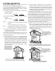
If suspending the furnace from rafters or joist, use 3/8”
threaded rod and 2”x2”x1/8” angle iron as shown in the fol-
a concrete pad. Never install the furnace on the ground or
allow it to be exposed to water. The length of rod will depend
on the application and the clearances necessary.
2" 2" 1/8"
ANGLE
IRON
(3
PLACES
)
X X
GAS
PIPING
When an existing furnace is removed from a venting
system serving other appliances, the venting system may be
too large to properly vent the remaining attached appliances.
The following vent testing procedure is repro duced from the
-
The following steps shall be followed with each appliance
connected to the venting system placed in operation, while
any other appliances connected to the venting system are
not in operation:
a. Seal any unused openings in the venting system.
b. Inspect the venting system for proper size and
horizontal pitch, as required by the National Fuel
Gas Code, ANSI Z223.1 or the CSA B149 Installa-
tion Codes and these instructions. Determine that
there is no blockage or restriction, leakage, corro-
unsafe condition.
c. In so far as practical, close all building doors
and windows and all doors between the space
in which the appliance(s) connected to the vent-
ing system are located and other spaces of the
building. Turn on clothes dryers and any appli-
ance not connected to the venting system. Turn
on any exhaust fans, such as range hoods and
bathroom exhausts, so they shall operate at max-
imum speed. Do not operate a summer exhaust
d. Follow the lighting instructions. Place the appli-
ance being inspected in operation. Adjust thermo-
stat so appliance shall operate continuously.