
Installation Instructions


11
the transition from 2" to 3" should be done as close to the
furnace as practically possible.
This furnace must not be connected to Type B, BW, or L vent or
vent connector, and must not be vented into any portion of a
factory built or masonry chimney except when used as a pathway
for PVC as described later in this section. Never common vent
this appliance with another appliance or use a vent which is used
by a solid fuel appliance. Do not use commercially available “no
hub connectors” other than those shipped with this product.
It is the responsibility of the installer to follow the manufactur-
ers’ recommendations and to verify that all vent/flue piping and
connectors are compatible with furnace flue products. Addition-
ally, it is the responsibility of the installer to ensure that all piping
and connections possess adequate structural integrity and sup-
port to prevent flue pipe separation, shifting, or sagging during
furnace operation.
DUAL CERTIFICATION: NON-DIRECT/DIRECT VENT
This furnace is dual certified and may be installed as a non-direct
vent (single pipe) or direct vent (dual pipe) appliance. A non-
direct vent installation requires only a vent/flue pipe, while a
direct vent installation requires both a vent/flue pipe and a com-
bustion air intake pipe. Refer to the appropriate section for
details concerning piping size, length, number of elbows, fur-
nace connections, and terminations.
MATERIALS AND JOINING METHODS
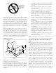
T
O
AVOID
BODILY
INJURY
,
FIRE
OR
EXPLOSION
,
SOLVENT
CEMENTS
MUST
BE
KEPT
AWAY
FROM
ALL
IGNITION
SOURCES
(
I
.
E
.,
SPARKS
,
OPEN
FLAMES
,
AND
EXCESSIVE
HEAT
)
AS
THEY
ARE
COMBUSTIBLE
LIQUIDS
.
A
VOID
BREATHING
CEMENT
VAPORS
OR
CONTACT
WITH
SKIN
AND
/
OR
EYES
.
WARNING
Two-three-inch nominal diameter PVC Schedule 40 pipe meet-
ing ASTM D1785, PVC primer meeting ASTM F656, and PVC
solvent cement meeting ASTM D2564 specifications must be
used. Fittings must be DWV type fittings meeting ASTM
D2665 and ASTM D3311. Carefully follow the manufacturer’s
instructions for cutting, cleaning, and solvent cementing of
PVC.
The use of Schedule 40 PVC cellular core DWV meeting ASTM
F891-1 or ABS cellular core (Foam Core) plastic pipe is also
acceptable as a flue/vent and intake pipe material. PVC
primer meeting ASTM F656 and PVC solvent cement meeting
ASTM D2564 specifications must be used. Fittings must be
DWV type fittings meeting ASTM D2665 and ASTM D3311.
Carefully follow the manufactures instructions for cutting,
cleaning and solvent cementing of PVC.
For Canadian Installations; field supplied PVC venting mate-
rials must be UL S636 listed. NOTE: Requirement does not
apply to the combustion air pipe.
As an alternative to PVC pipe, primer, solvent cement, and fit-
tings, ABS materials which are in compliance with the following
specifications may be used. Two-or-three-inch ABS Schedule 40
pipe must meet ASTM D1527 and, if used in Canada, must be
CSA listed. Solvent cement for ABS to ABS joints must meet
ASTM D2235 and, if used in Canada, must be CSA listed. The
solvent cement for the PVC to ABS transition joint must meet
ASTM D3138. Fittings must be DWV type fittings meeting ASTM
D2661 and ASTM D3311 and, if used in Canada, must be CSA
listed. Carefully follow the manufacturers’ instructions for cut-
ting, cleaning, and solvent cementing PVC and/or ABS.
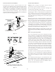
All 90° elbows must be medium radius (1/4 bend DWV) or long
radius (Long sweep 1/4 bend DWV) types conforming to ASTM
D3311. A medium radius (1/4 bend DWV) elbow measures 3 1/
16” minimum from the plane of one opening to the center line of
the other opening for 2” diameter pipe, and 4 9/16” minimum
for 3” pipe.
PROPER VENT/FLUE AND COMBUSTION AIR PIPING PRACTICES
Adhere to these instructions to ensure safe and proper furnace
performance. The length, diameter, and number of elbows of the
vent/flue pipe and combustion air pipe (when applicable) affects
the performance of the furnace and must be carefully sized. All
piping must be installed in accordance with local codes and these
instructions.
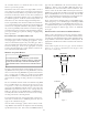
Some models require the use of 3” pipe. Do not transition
from a 2” to 3” pipe in a horizontal section of pipe as this
may create a water trap.
PREFERRED
Figure 4
TRANSITION NO LESS
THAN 45 DEGREES TO
HORIZONTAL PLANE TO
AVOID CREATING A WATER
TRAP IN VENT PIPING.
ACCEPTABLE
Figure 5