
Installation Guide


14
CONNECTION OF 24 VOLT HUMIDIFIER
The integrated control module single humidifier terminal “24
VHUM” is energized with 24 volts whenever the induced draft
blower is energized. Connect the common side of the 24 volt hu-
midifier to the “C” terminal of the thermostat terminal strip on
the control board.
HIGH VOLTAGE !
T
O
AVOID
PERSONAL
INJURY
OR
DEATH
DUE
TO
ELECTRICAL
SHOCK
,
DISCONNECT
ELECTRICAL
POWER
BEFORE
SERVICING
OR
CHANGING
ANY
ELECTRICAL
WIRING
.
WARNING
24 VAC HUMIDIFIER
The yellow wire connected to the I.D. Blower pressure switch is
powered anytime the pressure switch is closed and provides 24
VAC humidifier control. Remove the yellow wire and connect a
field supplied jumper wire with a “piggyback” terminal to the
pressure switch terminal. Reconnect the yellow wire to the
“piggyback” terminal on the jumper wire and then connect the 24
VAC line of the humidifier to the stripped end of the jumper wire.
Using a wire nut or a field-supplied quick connect terminal can
make this connection. The wiring must conform to all local and
national codes. Connect the COM side of the humidifier to the C
terminal on the low voltage terminal strip (where thermostat wires
are connected) of the furnace control board. DO NOT CONNECT
115V HUMIDIFIER TO THESE TERMINALS.
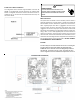
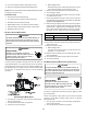
TWINNING
Furnaces may be twinned without the use of a twinning kit.
Furnaces must be the same model and equipped with
PCBBF145 control boards. Follow the diagram provided in
this manual. Connection of the “twin” terminals of each
control together will allow simultaneous operation of two or
TWINNING C ONNECTION D IAGRAM