
Installation Guide


16
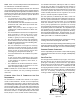
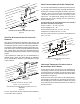
in
line with the induced draft blower outlet. To use the al-
NOTE: In the horizontal left installation position, a means
of condensate collection must be provided to keep vent
pipe condensate from entering the draft inducer housing.
If the vent drain elbow is eliminated from the installation,
on top the furnace.
2. Remove the internal elbow and vent pipe
4. Remove plastic plug in line with the inducer outlet
inducer with rubber coupling supplied with furnace.
cabinet.
B
E
SURE
NOT
TO
DAMAGE
INTERNAL
WIRING
OR
OTHER
COMPONENTS
WHEN
REINSTALLING
COUPLING
AND
SCREWS
.
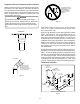
CAUTION
(Upow / Horizontal models only)
-
izontal left side down installation or a vertical installation
using down – venting, an alternate combustion air opening
can be used. A locating dimple is located on the right side
of the furnace cabinet. The locating dimple is 1 7/8” mea-
sured from the front edge of the cabinet in line with the
knock out. To use the alternate combustion air location:
1. Remove screws and combustion air flange from
cabinet.
2. Insert cabinet plug in unused combustion air hole.
4. Use a knockout tool to create a 3” diameter hole
removed in step one.
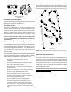
5 8
2 75 70 65 60 55 50 45 40
3
114 107 100 93 86 79 72 65
2 55 50 45 40 35 30 25 20
3 127 120 113 106 99 92 85 78
2^
30
25 20
15 10 5
N/A
N/A
3^
72
65 58 51 44 37 30 23
2^
30 25 20 15 10 5 N/A N/A
3^
72 65 58 51 44 37 30 23
2^
40 35 30 25 20 15 10 5
3 72 65 58 51 44 37 30 23
2 60 55 50 45 40 35 30 25
3 168 161 154 147 140 133
126 119
2 30 25 20 15 10 5 N/A N/A
3 113 106
99 92 85 78 71 64
2 N/A N/A N/A N/A N/A N/A N/A N/A
3 65 58 51 44 37 30 23 16
7,000 ft altitude or above use 3" pipe
^ *MES920402BN - add 20' of 2" pipe for upflow position
^ *MES920803BN - add 10' of 2" pipe for upflow position, add 66' of 3" pipe for upflow position
^ *MES920804CN - add 25' of 2" pipe for upflow position, add 58' of 3" pipe for upflow position
^ *MES920805CN - add 15' of 2" pipe for upflow position, add 58' of 3" pipe for upflow position
1. Maximum allowable limits listed on individual lengths
feet in length and one elbow/tee.
3. Tee used in the vent/flue termination must be
included when determining the number of elbows
in the piping system.
4. 2 ½” or 3” diameter pipe can be used in place of 2”
diameter pipe.
elbow.
6. One 90° elbow should be secured to the combustion
air intake connection.