
Installation Guide


19
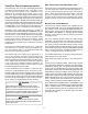
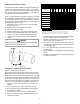
90°
ELBOWS
12" MIN. ABOVE
HIGHEST ANTICIPATED
SNOW LEVEL
3” - 24”
Refer to the following table for applicable length, elbows, and
The number of elbows tabulated represents the number of el-
pipe. Elbows and/or tees used in the terminations must be
included when determining the number of elbows in the piping
systems.
If the combustion air intake pipe is to be installed above a
will be objectionable, insulation of the combustion air pipe
may be required.
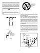
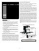
90°
ELBOWS
12" MIN. ABOVE
HIGHEST ANTICIPATED
SNOW LEVEL
3”-24” BETWEEN PIPES
Combustion Air Intake may also be snorkeled
to obtain 12” min ground clearance.
-
ly, as through a roof, or horizontally, as through an outside wall.
-
Refer to Vent/Flue Pipe and Combustion Pipe
- Termination Locations for details concerning location
restrictions. The penetrations through the roof must be
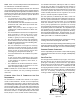
plastic plumbing vent.
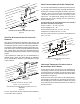
Center to center = 10” min / 24” max.
Combustion air intake from wall = 6” max.
level = 12” min.
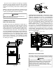
3” MIN
12” MIN TO GRADE OR HIGHEST
ANTICIPATED SNOW LEVEL
3”MIN
24”MAX
12” M I N SEPARATION
Termination of
If more than one direct vent furnace is to be installed verti-
cally through a common roof top, maintain the same minimum
clearances between the exhaust vent and air intake termina-
tions of adjacent units as with the exhaust vent and air intake
terminations of a single unit.
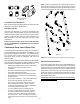
If more than one direct vent furnace is to be installed horizon-
tally through a common side wall, maintain the clearances as in
at the same elevation and always terminate all air intakes at
the same elevation.