
Installation Guide


36
contacts to provide a call for heat.
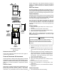
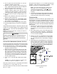
7. Measure the gas manifold pressure with burners
Manifold
Gas Pressure table shown on this page.
8. Remove regulator cover screw from the outlet
pressure regulator adjust tower and turn screw
clockwise to increase pressure or counterclockwise
to decrease pressure. Replace regulator cover screw.
system.
10. Remove the manometer hose from the hose barb
valve: Turn outlet pressure test screw in to seal pressure
12. Turn on electrical power and gas supply to the system.
valve.
Using a leak detection solution or soap suds, check for leaks
appropriate conversion.
CAUTION
T
O
PREVENT
UNRELIABLE
OPERATION
OR
EQUIPMENT
DAMAGE
,
THE
INLET
GAS
SUPPLY
PRESSURE
MUST
BE
AS
SPECIFIED
ON
THE
UNIT
RATING
PLATE
WITH
ALL
OTHER
HOUSEHOLD
GAS
FIRED
APPLIANCES
OPERATING
.
The actual gas input rate to the furnace must never be greater
gas input using the gas meter, use the following procedure.
appliances except the furnace.
and record one complete revolution of the gas meter
dial, measuring the smallest quantity, usually the dial
this number to calculate the quantity of gas in cubic
ft. if the furnace would consume if it ran steadily for
3. If the 1/2 cu. ft. dial was used, multiply your number
x 2.
This tells us that at this rate, it would take 46 seconds to
consume one cu. ft. of gas. 3600 / 46 = 78.
This tells us that in one hour, the furnace would consume
78 cu. ft. of gas.
The typical value range for 1 cu. ft. of natural gas is around
1000 BTU. Check with your gas utility, if possible. In this
example, the furnace is consuming 78,000 BTUH.
more than ± 0.3” w.c. for Natural and + 0.5” for
gas supplier if additional input rate adjustment is
required.
in step 1. Be certain that all appliances are functioning
properly and that all pilot burners are operating.
unit rating plate. An incorrect temperature rise may result in
rise as follows:
ten minutes. Ensure all registers are open and all
position.
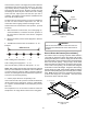
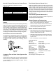
2. Place thermometers in the return and supply ducts
as close to the furnace as possible. Thermometers
to “see” the heat exchanger.
3. Subtract the return air temperature from the supply
air temperature to determine the air temperature
rise. Allow adequate time for thermometer readings to
stabilize.
4. Adjust temperature rise by adjusting the circulator blower
speed. Increase blower speed to reduce temperature
rise. Refer to Startup Procedure and Adjustment
-Circulator Blower Speeds for speed changing details.
SUPPLY
AIR
RETURN
AIR
Temperature Rise Measurement