
Installation Guide


37
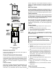
The integrated control module on 96% models provides a se-
may be set to 100 or 150 seconds by cutting the jumper
on the control module. The delay is factory shipped at
150 seconds but may be changed to suit the installation
requirements and/or homeowner preference.
The normal power up sequence is as follows:
• Integrated control module performs internal
checks.
• Integrated control module monitors safety circuits
continuously.
The normal operational sequence in heating mode is as follows:
for heat.
• Integrated control module performs safety circuit
checks
• Induced draft blower is energized for a 15-second
prepurge.
• Igniter warn up begins upon presence of closed
pressure switch contacts.
• Gas valve opens at end of igniter warm up period,
• Circulator blower is energized on heat speed
safety circuits continously.
call for heat.
• Induced draft blower is de-energized following a
• 96% models HUM terminal is de-energized.
• Circulator blower continues
• EAC terminal is de-energized
The normal operational sequence in cooling mode is as follows:
for cool.
• Integrated control module performs safety circuit
checks.
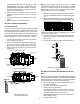
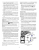
This furnace is equipped with a multi-speed circulator blow-
er. This blower provides ease in adjusting blower speeds.
of heating and cooling speeds.
T
O
AVOID
PERSONAL
INJURY
OR
DEATH
DUE
TO
ELECTRICAL
SHOCK
,
TURN
OFF
POWER
TO
THE
FURNACE
BEFORE
CHANGING
SPEED
TAPS
.
WARNING
with the furnace. If the cooling capacity is in BTU/hr
divide it by 12,000 to convert capacity to tons.
Cooling Capacity of 30,000 BTU/hr.
30,000/12,000 = 2.5 Tons
Most cooling systems are designed to work with air
3. Select the heating speed for your model from the
selected speed must provide a temperature rise
within the rise range listed with the particular model.
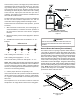
To adjust the circulator blower speed, proceed as follows:
2. Select the heating and cooling blower speeds that
match the installation requirements from the airow
table in the Specication Sheet.
3. Relocate desired motor leads to the circulator blower
heat and cool speed terminals on the integrated
the same, a jumper wire must be used between the
heat and cool terminals.
terminals on the integrated control module. Any
be taped.
5. Turn ON power to furnace.
Temperature Rise section of Startup Procedure and
Adjustment.
In general lower heating speeds will: reduce electrical consump-
tion, lower operating sound levels of the blower, and increase
the outlet air temperature delivered to the home. The speeds
available allow the blower performance to be optimized for the
particular homeowner’s needs.