
Installation Guide


41
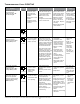
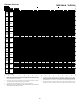
due to an excessive
number of ignition
1
.
• Locate and correct gas
interruption.
• Check front cover
pressure switch oper-
Correct if necessary.
• Replace or realign
igniter.
signal. Sand sensor
if coated and/or oxi-
dized.
for blockage, proper
length, elbows, and
termination.
draft blower perfor-
mance.
• Turn power
repair.
• Igniter is
fragile, handle
with care.
sensor with
emery cloth.
-
tion for piping
details.
• Integrated control
module diagnostic is
1
Cause may be no gas to
burners, front cover pres-
sure switch stuck open, bad
igniter or igniter alignment,
-
ed/oxidized or improperly
-
lishment. Cause may be
interrupted gas supply, lazy
gas pressure or restriction
pressure switch opening,
or improper induced draft
blower performance.
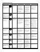
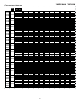
• Pressure switch
circuit is closed.
• Induced draft
blower
operating.
prior to repair.
• Replace pressure
switch with prop-
er replacement
part.
• Integrated control
module diagnostic is
2
• Induced draft blower
pressure switch contacts
sticking.
• Shorts in pressure switch
circuit.
• Pressure switch hose
blocked, pinched or con-
nected improperly.
air pipe, blocked drain
system, or weak induced
draft blower.
• Incorrect pressure switch
setpoint or malfunctioning
switch contacts.
• Loose or improperly con-
nected wiring.
• Pressure switch
circuit not closed.
• Induced draft blow-
er operating.
• Induced draft blower runs
continuously with no fur-
ther furnace operation.
• Integrated control module
diagnostic
• Turn power
repair.
• Replace pres-
sure switch
with proper
replacement
part.
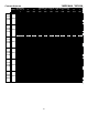
• Normal Operation
• Normal Operation
• None
• Normal Operation
• No 115 volt power
to furnace, or no
24 volt power to
integrated control
module.
• Blown fuse or circuit
breaker.
• Integrated control
module has an inter-
nal fault.
• Manual disconnect switch
24 volt wires improperly
connected or loose.
• Blown fuse or circuit
breaker.
• Integrated control module
has an internal fault.
• Assure 115 and 24 volt
power to furnace inte-
grated control module.
• Check integrated con-
Replace if necessary.
• Check for possible
shorts in 115 and 24
volt circuits. Repair as
necessary.
• Replace bad integrated
control module.
prior to repair.
• Replace
integrated
control module
fuse with 3A auto-
motive fuse.
• Read precautions
in “Electrostatic
of manual.
• Integrated control
module diagnostic
provides .
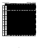
NONE
• Replace induced
draft blower pressure
switch.
• Repair short.
• Inspect pressure switch
hose. Repair, if neces-
sary,
air piping for blockage,
proper length, elbows,
and termination. Check
drain system. Correct as
necessary.
• Correct pressure switch
setpoint or contact
motion.
• Tighten or correct wiring
connection.
ON
CONTINUOUS
ON
Integrated control module will automatically attempt to reset from lockout after one hour.
2
3