INSTALLATION INSTRUCTIONS FOR *MEC80* & *CEC80 GAS FURNACE (Type FSP CATEGORY I Direct or Non Direct Vent Air Furnace) (Type FSP CATÉGORIE I Direct ou f our á air souf fl é non direct ) These f ur naces compl y w i t h r equi r ement s embodied in t he American Nat ional St andard / Nat ional St andard of Canada ANSI Z21. 47· CSA-2. 3 Gas Fired Cent ral Furnaces. Installer: Affix all manuals adjacent to the unit.
Always install a furnace to operate within the furnace’s intended temperature-rise range with a duct system which has external static pressure within the allowable range, as specified on the furnace rating plate and OPERATIONAL CHECKS section of these instructions. SAFETY CONSIDERATIONS Adhere to the following warnings and cautions when installing, adjusting, altering, servicing, or operating the furnace.
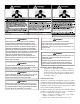
RISQUE D'EMPOISONNEMENT AU MONOXYDE DE CARBONE Advertencia especial para la instalación de calentadores ó manejadoras de aire en áreas cerradas como estacionamientos ó cuartos de servicio. Las emisiones de monóxido de carbono pueden circular a través del aparato cuando se opera en cualquier modo. CO can cause serious illness including permanent brain damage or death.
maximum CFM, and motor speed connections, and venting. These furnaces are designed for Category I venting only. 3. With concealed damage, carrier must be notified as soon as possible - preferably within five days. 4. File the claim with the following support documents within a nine month statute of limitations. • Original or certified copy of the Bill of Lading, or indemnity bond. • Original paid freight bill or indemnity in lieu thereof.
• • • Combustion and Ventilation Air The furnace heat exchanger, components, duct system, air filters and evaporator coils are thoroughly cleaned following final construction clean up by a qualified person.
• Exposure to contaminated combustion air will result in safety and performance-related problems. Do not install the furnace where the combustion air is exposed to the following substances: Do not install the furnace directly on carpeting, tile, or other combustible material other than wood flooring. (NOTE: The subbase will not be required if an air conditioning coil is installed between the supply air opening on the furnace and the floor.
HORIZONTAL INSTALLATION EXISTING FURNACE REMOVAL Line contact to framing is permitted when installed in the horizontal configuration. Line contact is defined as the portion of the cabinet that is formed by the intersection of the top and side. ACCESSIBILITY CLEARANCE, WHERE GREATER, SHOULD TAKE PRECEDENCE OVER MINIMUM FIRE PROTECTION CLEARANCE.
If resizing is required on any portion of the venting system, use the appropriate table in the latest edition of the National Fuel Gas Code ANSI Z223.1. AVERTISSEMENT RISQUE D'INTOXICATION AU MONOXYDE DE CARBONE Si les étapes décrites ci-dessous ne sont pas suivies pour chacun des appareils raccordés au système de ventilation au moment de sa mise en marche, cela peut entraîner une intoxication au monoxyde de carbone ou la mort.
THIS PRODUCT IS NOT DESIGNED FOR COUNTERCLOCKWISE INDUCED DRAFT BLOWER ROTATION. Most homes will require outside air be supplied to the furnace area by means of ventilation grilles or ducts connecting directly to the outdoors or spaces open to the outdoors such as attics or crawl spaces. CATEGORY I VENTING (VERTICAL VENTING) Vent the furnace in accordance with the National Fuel Gas Code NFPA 54/ANSI Z223.1 - latest edition. Venting WARNING THIS FURNACE IS NOT DESIGN CERTIFIED TO BE HORIZONTALLY VENTED.
This checklist is only a summary. For detailed information on each of the procedures mentioned, see the paragraph referenced with each item. EXTERIOR MASONRY CHIMNEYS (CATEGORY I FURNACES ONLY) An exterior masonry chimney is defined as a “Masonry” chimney exposed to the outdoors on one or more sides below the roof line.” The ability to use a clay lined masonry chimney depends on a parameter not associated with interior chimneys. This variable is the geographic location of the installation.
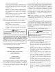
If the chimney does not meet these termination requirements, Liquid fuel appliances include oil furnaces, oil-fired boilers and but all other requirements in the checklist can be met, it may oil-fired water heaters. be possible for a mason to extend the chimney. If this will not Appliances which burn propane (sometimes referred to as LP be practical, see Fix 1. (liquefied petroleum)) gas are considered gas-fired appliances. 10' or Less CHECK 3 - CHIMNEY CROWN CONDITION. 2' Min. 2' Min. 3' Min.
Next, use a flashlight and small mirror to sight up the liner. B vent must be supported so as to not come into direct contact with the chimney walls or tile liner. If it is not, it can probably be rehung so as to be acceptable. A thimble or fire stop may be helpful here. CSA B149.2 - latest editions and amendments, then the clay tile liner can probably be used as a vent for the gas appliances.
FIX 4 - RELINING Relining options include B vent and flexible liners. If the chimney has diagonal offsets, B vent probably cannot be used. If B vent is to be used, it must be supported adequately. Supports (such as fire stops or thimbles) must be used to prevent the B vent from coming into direct contact with the tile liner or chimney walls. Direct contact would result in higher heat loss, with an increased possibility of poor venting system performance.
115 VOLT LINE CONNECTIONS WARNING Before proceeding with electrical connections, ensure that the supply voltage, frequency, and phase correspond to that specified on the unit rating plate. Power supply to the furnace must be NEC Class 1, and must comply with all applicable codes. The furnace must be electrically grounded in accordance with local codes or, in their absence, with the latest edition of The National Electric Code, ANSI NFPA 70 and/or The Canadian Electric Code CSA C22.1.
At all altitudes, the manifold pressure must be within 0.3 inches w.c. of that listed in the Specification Sheet applicable to your model for the fuel used. At all altitudes and with either fuel, the air temperature rise must be within the range listed on the furnace nameplate. Should this appliance be converted to LP, refer to the instructions included in the factory authorized LP conversion kit. When sizing gas lines, be sure to include all appliances which will operate simultaneously.
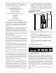
– – Rigid metallic pipe and fittings. COUNTERFLOW INSTALLATIONS Semi-rigid metallic tubing and metallic fittings. Aluminum alloy tubing must not be used in exterior locations. When the gas piping enters through the left side of the furnace, the installer must supply a straight pipe and a 90 degree elbow to reach the exterior of the furnace. – Use listed gas appliance connectors in accordance with their instructions. Connectors must be fully in the same room as the furnace.
Manual 58. PROPANE GAS PIPING CHARTS For satisfactory operation, propane gas pressure must be 10 inch WC at the furnace manifold with all gas appliances in operation. Maintaining proper gas pressure depends on three main factors: 1. Vaporization rate, depending on temperature of the liquid, and “wetted surface” area of the container or containers. Sizing Between First and Second Stage Regulator* Maximum Propane Capacities listed are based on 2 psig pressure drop at 10 psig setting.
When the furnace is used in connection with a cooling unit, the furnace should be installed in parallel with or on the upstream side of the cooling unit to avoid condensation in the heating element. With a parallel flow arrangement, the dampers or other means used to control the flow of air must be adequate to prevent chilled air from entering the furnace and, if manually operated, must be equipped with means to prevent operation of either unit unless the damper is in the full heat or cool position.
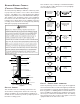
CIRCULATION AIR FILTERS Upflow / Horizontal Models *MEC80403B* *MEC80603B* *MEC80604B* *MEC80803B* *MEC80804C* *MEC80805C*¹ *MEC80805D*¹ *MEC81005C* *MEC81005C* Downflow / Horizontal Models *CEC80403B* *CEC80603B* *CEC80805C* *CEC81005C* Figure 11 Minimum Recommended Filter Size^ 1 - 16 X 25 Side or 1 - 14 X 24 Bottom Return 1 - 16 X 25 Side or 1 - 14 X 24 Bottom Return 1 - 16 X 25 Side or 14 X 24 Bottom Return 1 - 16 X 25 Side or Bottom Return 1 - 16 X 25 Side or Bottom Return 1 - 16 X 25 Side or Bottom
pump. Refer to the fossil fuel kit installation instructions for additional thermostat requirements. Figure 16 R R Y Strictly follow the wiring guidelines in the fossil fuel kit installation instructions. All furnace connections must be made to the furnace two-stage integrated control module and the “FURNACE” terminal strip on the fossil fuel control board.
air cleaner neutral terminals are identified as NEUTRAL. All field wiring must conform to applicable codes. Connections should be made as shown. If it is necessary for the installer to supply additional line voltage wiring to the inside of the furnace, the wiring must conform to all local codes, and have a minimum temperature rating of 105°C. All line voltage wire splices must be made inside the furnace junction box.
proper furnace operation. All conversions must be performed by a qualified installer, or service agency. CAUTION TO PREVENT UNRELIABLE OPERATION OR EQUIPMENT DAMAGE , THE INLET GAS SUPPLY PRESSURE MUST BE AS SPECIFIED ON THE UNIT RATING PLATE WITH ALL OTHER HOUSEHOLD GAS FIRED APPLIANCES OPERATING. • Use black iron or steel pipe and fittings for building piping. Where possible, use new pipe that is properly chamfered, reamed, and free of burrs and chips.
long nipple is required. PROPANE GAS TANKS AND PIPING A semi-rigid connector to the gas piping can be used outside the cabinet per local codes. From the elbow, the length of pipe and the fittings required will vary by the side chosen, location of union and cabinet width. The union may be placed inside or outside of the cabinet.
3. The difference between the two numbers is .4” w.c. Example: DUCT WORK - AIR FLOW static reading from return duct = -.1” w.c. Duct systems and register sizes must be properly designed for the static reading from supply duct = .3” w.c. CFM and external static pressure rating of the furnace. Design the total external static pressure on this system = .4” w.c. ductwork in accordance with the recommended methods of “Air Conditioning Contractors of America” Manual D.
Air Cleaner Installation Location Maximum Heating Airflow Filter (Media) Dimensions Part Number Si de or bottom return 1200 CFM 16 i n X 20 i n x 5¼" AM11-1620-5 Si de or bottom return 1600 CFM 16 i n X 25 i n x 5¼" AM11-1625-5 Si de or bottom return 1600 CFM 20 i n X 20 i n x 5¼" AM11-2020-5 Si de or bottom return 2000 CFM 20 i n X 25 i n x 5¼" AM11-2025-5 2 X 1600 CFM 2, 16 i n X 25 i n x 5¼" AM11-3225-5 AM11-3225 Si de return (Ri ght a ngl e) 2000 CFM 20 i n X 25 i n x 5¼" AM11
3. Turn ON the gas supply and operate the furnace and all other gas consuming appliances on the same gas supply line. 4. Measure furnace gas supply pressure with burners firing. Supply pressure must be within the range specified in the Inlet Gas Supply Pressure table. GAS SUPPLY PRESSURE MEASUREMENT If supply pressure differs from table, make the necessary adjustments to pressure regulator, gas piping size, etc., and/or consult with local gas utility.
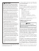
Measuring Inlet Gas Pressure (Alt. Method) Figure 24 NOTE: When converting from natural gas to L.P. consult your distributor for proper conversion kit. Manifold Gas Pressure Gas Natural Propane Range Nominal Low Stage 1.6 - 2.2" w.c. 1.9" w.c. High Stage 3.2 - 3.8" w.c. 3.5" w.c. Low Stage 5.7 - 6.3" w.c. 6.0" w.c. High Stage 9.7 - 10.3" w.c. 10.0" w.c.
AIRFLOW TABLES GCEC800403AN PCBBF139 DIP Switches STATIC S1-1 S1-2 S1-3 T STAT CALL Ylo OFF OFF OFF* Y Ylo ON OFF OFF Y Ylo ON ON OFF Y Ylo OFF ON OFF Y Ylo OFF OFF ON Y Ylo OFF ON ON Y Ylo ON OFF ON Y Ylo ON ON ON Y 0.1 CFM 785 1348 663 785 663 1348 785 591 785 1104 663 591 1104 1348 1104 663 0.2 CFM 754 1294 647 754 647 1294 754 568 754 1058 647 568 1058 1294 1058 647 *CEC800403A* - COOLING 0.3 0.4 0.
AIRFLOW TABLES GCEC800603AN PCBBF139 DIP Switches STATIC S1-1 S1-2 S1-3 T STAT CALL Ylo OFF OFF OFF* Y Ylo ON OFF OFF Y Ylo ON ON OFF Y Ylo OFF ON OFF Y Ylo OFF OFF ON Y Ylo OFF ON ON Y Ylo ON OFF ON Y Ylo ON ON ON Y 0.1 CFM 1160 1411 656 1160 656 1411 1160 716 1160 1054 656 716 1054 1411 1054 656 0.2 CFM 1102 1356 589 1102 589 1356 1102 647 1102 1002 589 647 1002 1356 1002 589 *CEC800603A*- COOLING 0.3 0.4 0.
AIRFLOW TABLES GCEC800603BN PCBBF139 DIP Switches STATIC S1-1 S1-2 S1-3 T STAT CALL Ylo OFF OFF OFF* Y Ylo ON OFF OFF Y Ylo ON ON OFF Y Ylo OFF ON OFF Y Ylo OFF OFF ON Y Ylo OFF ON ON Y Ylo ON OFF ON Y Ylo ON ON ON Y 0.1 CFM 1223 1395 1032 1223 1032 1395 1223 1025 1223 1258 1032 1025 1258 1395 1258 1032 0.2 CFM 1144 1332 800 1144 800 1332 1144 850 1144 1179 800 850 1179 1332 1179 800 *CEC800603B* - COOLING 0.3 0.4 0.
AIRFLOW TABLES GCEC800804BN PCBBF139 DIP Switches STATIC S1-1 S1-2 S1-3 T STAT CALL Ylo OFF OFF OFF* Y Ylo ON OFF OFF Y Ylo ON ON OFF Y Ylo OFF ON OFF Y Ylo OFF OFF ON Y Ylo OFF ON ON Y Ylo ON OFF ON Y Ylo ON ON ON Y 0.1 CFM 1596 1757 784 1596 784 1757 1596 1040 1596 1401 784 1040 1401 1757 1401 784 0.2 CFM 1553 1713 716 1553 716 1713 1553 973 1553 1366 716 973 1366 1713 1366 716 *CEC800804B* - COOLING 0.3 0.4 0.
AIRFLOW TABLES GCEC800805CN PCBBF139 DIP Switches STATIC S1-1 S1-2 S1-3 T STAT CALL Ylo OFF OFF OFF* Y Ylo ON OFF OFF Y Ylo ON ON OFF Y Ylo OFF ON OFF Y Ylo OFF OFF ON Y Ylo OFF ON ON Y Ylo ON OFF ON Y Ylo ON ON ON Y 0.1 CFM 1782 2145 1171 1782 1171 2145 1782 1175 1782 1547 1171 1175 1547 2145 1547 1171 0.2 CFM 1744 2089 884 1744 884 2089 1744 1098 1744 1506 884 1098 1506 2089 1506 884 *CEC800805C* - COOLING 0.3 0.4 0.
AIRFLOW TABLES GMEC-GCEC801005CN PCBBF139 DIP Switches STATIC S1-1 S1-2 S1-3 T STAT CALL Ylo OFF OFF OFF* Y Ylo ON OFF OFF Y Ylo ON ON OFF Y Ylo OFF ON OFF Y Ylo OFF OFF ON Y Ylo OFF ON ON Y Ylo ON OFF ON Y Ylo ON ON ON Y 0.1 CFM 1820 2235 803 1820 803 2235 1820 1626 1820 2169 803 1626 2169 2235 2169 803 0.2 CFM 1769 2185 719 1769 719 2185 1769 1574 1769 2116 719 1574 2116 2185 2116 719 **EC801005C* - COOLING 0.3 0.4 0.
AIRFLOW TABLES GCEC800804BN PCBBF139 *CEC800403A* - COOLING DIP Switches STATIC S1-1 S1-2 S1-3 T STAT CALL Ylo OFF OFF OFF* Y Ylo ON OFF OFF Y Ylo ON ON OFF Y Ylo OFF ON OFF Y Ylo OFF OFF ON Y Ylo OFF ON ON Y Ylo ON OFF ON Y Ylo ON ON ON Y 0.1 CFM 785 1348 663 785 663 1348 785 591 785 1104 663 591 1104 1348 1104 663 0.
AIRFLOW TABLES GMEC800403AN PCBBF139 DIP Switches STATIC S1-1 S1-2 S1-3 T STAT CALL Ylo OFF OFF OFF* Y Ylo ON OFF OFF Y Ylo ON ON OFF Y Ylo OFF ON OFF Y Ylo OFF OFF ON Y Ylo OFF ON ON Y Ylo ON OFF ON Y Ylo ON ON ON Y 0.1 CFM 1138 1367 923 1138 923 1367 1138 553 1138 750 923 553 750 1367 750 923 0.2 CFM 1093 1321 865 1093 865 1321 1093 496 1093 703 865 496 703 1321 703 865 *MEC800403A* - COOLING 0.3 0.4 0.
AIRFLOW TABLES GMEC800603AN PCBBF139 DIP Switches STATIC S1-1 S1-2 S1-3 T STAT CALL Ylo OFF OFF OFF* Y Ylo ON OFF OFF Y Ylo ON ON OFF Y Ylo OFF ON OFF Y Ylo OFF OFF ON Y Ylo OFF ON ON Y Ylo ON OFF ON Y Ylo ON ON ON Y 0.1 CFM 1151 1389 681 1151 681 1389 1151 1079 1151 1328 681 1079 1328 1389 1328 681 0.2 CFM 1091 1341 617 1091 617 1341 1091 1019 1091 1274 617 1019 1274 1341 1274 617 *MEC800603A* - COOLING 0.3 0.4 0.
AIRFLOW TABLES GMEC800603BN PCBBF139 DIP Switches STATIC S1-1 S1-2 S1-3 T STAT CALL Ylo OFF OFF OFF* Y Ylo ON OFF OFF Y Ylo ON ON OFF Y Ylo OFF ON OFF Y Ylo OFF OFF ON Y Ylo OFF ON ON Y Ylo ON OFF ON Y Ylo ON ON ON Y 0.1 CFM 1330 1465 737 1330 737 1465 1330 1155 1330 1418 737 1155 1418 1465 1418 737 0.2 CFM 1280 1416 661 1280 661 1416 1280 1100 1280 1376 661 1100 1376 1416 1376 661 *MEC800603B* - COOLING 0.3 0.4 0.
AIRFLOW TABLES GMEC800603BN PCBBF139 DIP Switches STATIC S1-1 S1-2 S1-3 T STAT CALL Ylo OFF OFF OFF* Y Ylo ON OFF OFF Y Ylo ON ON OFF Y Ylo OFF ON OFF Y Ylo OFF OFF ON Y Ylo OFF ON ON Y Ylo ON OFF ON Y Ylo ON ON ON Y 0.1 CFM 1160 1231 706 1160 706 1231 1160 1133 1160 1402 706 1133 1402 1231 1402 706 0.2 CFM 1107 1185 631 1107 631 1185 1107 1009 1107 1358 631 1009 1358 1185 1358 631 *MEC800803B* - COOLING 0.3 0.4 0.
AIRFLOW TABLES GMEC800804BN PCBBF139 DIP Switches STATIC S1-1 S1-2 S1-3 T STAT CALL Ylo OFF OFF OFF* Y Ylo ON OFF OFF Y Ylo ON ON OFF Y Ylo OFF ON OFF Y Ylo OFF OFF ON Y Ylo OFF ON ON Y Ylo ON OFF ON Y Ylo ON ON ON Y 0.1 CFM 1574 1782 743 1574 743 1782 1574 1130 1574 1408 743 1130 1408 1782 1408 743 0.2 CFM 1521 1726 668 1521 668 1726 1521 1071 1521 1369 668 1071 1369 1726 1369 668 *MEC800804B* - COOLING 0.3 0.4 0.
AIRFLOW TABLES GMEC800804CN PCBBF139 DIP Switches STATIC S1-1 S1-2 S1-3 T STAT CALL Ylo OFF OFF OFF* Y Ylo ON OFF OFF Y Ylo ON ON OFF Y Ylo OFF ON OFF Y Ylo OFF OFF ON Y Ylo OFF ON ON Y Ylo ON OFF ON Y Ylo ON ON ON Y 0.1 CFM 1466 1904 822 1466 822 1904 1466 1352 1466 1669 822 1352 1669 1904 1669 822 0.2 CFM 1399 1832 754 1399 754 1832 1399 1281 1399 1595 754 1281 1595 1832 1595 754 *MEC800804C* - COOLING 0.3 0.4 0.
AIRFLOW TABLES GMEC800805DN PCBBF139 DIP Switches STATIC S1-1 S1-2 S1-3 T STAT CALL Ylo OFF OFF OFF* Y Ylo ON OFF OFF Y Ylo ON ON OFF Y Ylo OFF ON OFF Y Ylo OFF OFF ON Y Ylo OFF ON ON Y Ylo ON OFF ON Y Ylo ON ON ON Y 0.1 CFM 1698 2266 1088 1698 1088 2266 1698 1450 1698 1886 1088 1450 1886 2266 1886 1088 0.2 CFM 1621 2202 999 1621 999 2202 1621 1382 1621 1822 999 1382 1822 2202 1822 999 *MEC800805D* - COOLING 0.3 0.4 0.
AIRFLOW TABLES GMEC800805CN PCBBF139 DIP Switches STATIC S1-1 S1-2 S1-3 T STAT CALL Ylo OFF OFF OFF* Y Ylo ON OFF OFF Y Ylo ON ON OFF Y Ylo OFF ON OFF Y Ylo OFF OFF ON Y Ylo OFF ON ON Y Ylo ON OFF ON Y Ylo ON ON ON Y 0.1 CFM 1583 2145 1171 1583 1171 2145 1583 1436 1583 1782 1171 1436 1782 2145 1782 1171 0.2 CFM 1536 2089 884 1536 884 2089 1536 1402 1536 1744 884 1402 1744 2089 1744 884 *MEC800805C* - COOLING 0.3 0.4 0.
AIRFLOW TABLES GMEC801004CN PCBBF139 DIP Switches STATIC S1-1 S1-2 S1-3 T STAT CALL Ylo OFF OFF OFF* Y Ylo ON OFF OFF Y Ylo ON ON OFF Y Ylo OFF ON OFF Y Ylo OFF OFF ON Y Ylo OFF ON ON Y Ylo ON OFF ON Y Ylo ON ON ON Y 0.1 CFM 1265 1598 789 1265 789 1598 1265 1424 1265 1810 789 1424 1810 1598 1810 789 0.2 CFM 1204 1547 719 1204 719 1547 1204 1378 1204 1764 719 1378 1764 1547 1764 719 *MEC801004C* - COOLING 0.3 0.4 0.
AIRFLOW TABLES GMEC801205DN PCBBF139 DIP Switches STATIC S1-1 S1-2 S1-3 T STAT CALL Ylo OFF OFF OFF* Y Ylo ON OFF OFF Y Ylo ON ON OFF Y Ylo OFF ON OFF Y Ylo OFF OFF ON Y Ylo OFF ON ON Y Ylo ON OFF ON Y Ylo ON ON ON Y 0.1 CFM 1627 2226 815 1627 815 2226 1627 1381 1627 1831 815 1381 1831 2226 1831 815 0.2 CFM 1566 2165 742 1566 742 2165 1566 1324 1566 1770 742 1324 1770 2165 1770 742 *MEC801205D* - COOLING 0.3 0.4 0.
WIRING DIAGRAM YL HIGH FIRE PRESSURE SWITCH C NO NO BK WH HI 3 C 2 PU DISCONNECT TO 115VAC/ 1Ø /60 HZ POWER SUPPLY WITH OVERCURRENT PROTECTION DEVICE OR FLAME SENSOR GY TWO STAGE GAS VALVE PM 1 (WHITE RODGERS) BR BL OR PU 2 1 GN INDUCED DRAFT BLOWER WH RD BK 3 JUNCTION BOX GND INDOOR AIR CIRCULATOR BLWR NEUTRAL LINE PK HUM-OUT 24V THERMOSTAT CONNECTIONS N.E.C.
HORIZONTAL UNIT FILTER REMOVAL MAINTENANCE Filters in horizontal installations are located in the central return register or the ductwork near the furnace. WARNING TO AVOID ELECTRICAL SHOCK , INJURY OR DEATH, To remove: 1. Turn OFF electrical power to furnace. 2. Remove filter(s) from the central return register or ductwork. 3. Replace filter(s) by reversing the procedure for removal. 4. Turn ON electrical power to furnace. DISCONNECT ELECTRICAL POWER BEFORE PERFORMING ANY MAINTENANCE.
REPAIR AND REPLACEMENT PARTS • When ordering any of the listed functional parts, be sure to provide the furnace model, manufacturing, and serial numbers with the order. • Although only functional parts are shown in the parts list, all sheet metal parts, doors, etc. may be ordered by description. • Parts are available from your distributor.
CUSTOMER FEEDBACK We are very interested in all product comments. Please fill out the feedback on one of the following links: Goodman® Brand Products: (http://www.goodmanmfg.com/about/contact-us). Amana® Brand Products: (http://www.amana-hac.com/about-us/contact-us). You can also scan the QR code on the right for the product brand you purchased to be direced to the feedback page. GOODMAN® BRAND AMANA® BRAND GOODMAN® BRAND AMANA® BRAND Product Registration Thank you for your recent purchase.