
Installation Guide

9
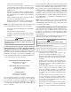
Most homes will require outside air be supplied to the furnace
area by means of ventilation grilles or ducts connecting directly
to the outdoors or spaces open to the outdoors such as attics
or crawl spaces.
CATEGORY I VENTING (VERTICAL VENTING)
T
O
PREVENT
POSSIBLE
PERSONAL
INJURY
OR
DEATH
DUE
TO
ASPHYXIATION
,
THIS
FURNACE
MUST
BE
C
ATEGORY
I
VENTED
. D
O
NOT
VENT
USING
C
ATEGORY
III
VENTING
.
WARNING
Category I Venting is venting at a non-positive pressure. A
furnace vented as Category I is considered a fan-assisted
appliance and the vent system does not have to be “gas
tight.” NOTE: Gas furnaces with induced draft blowers draw
products of combustion through a heat exchanger allowing,
in some instances, common venting with natural draft appli-
ances (i.e. water heaters). All installations must be vented
in accordance with National Fuel Gas Code NFPA 54/ANSI
Z223.1 - latest edition.
NOTE: The vertical height of the Category I venting system
must be at least as great as the horizontal length of the venting
system.
T
O
PREVENT
POSSIBLE
PERSONAL
INJURY
OR
DEATH
DUE
TO
ASPHYXIATION
,
COMMON
VENTING
WITH
OTHER
MANUFACTURER
’
S
INDUCED
DRAFT
APPLIANCES
IS
NOT
ALLOWED
.
WARNING
The minimum vent diameter for the Category I venting system
is as shown:
UPFLOW COUNTERFLOW
060 4 inch 4 inch
080 4 inch 4 inch
100 5 inch 4 inch
MINIMUM VENT
MODEL
Under some conditions, larger vents than those shown above
may be required or allowed. When an existing furnace is re-
moved from a venting system serving other appliances, the
venting system may be too large to properly vent the remaining
attached appliances.
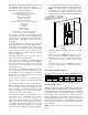
Furnaces are shipped with the induced draft blower discharg-
ing from the top of the furnace. (“Top” is as viewed for an
upfl ow installation.) The induced draft blower on *MEC80
models can be rotated 90 degrees for Category I venting. For
furnaces installed vertically or horizontally, a four-inch single
wall pipe can be used to extend the induced draft blower
outlet 1/2” beyond the furnace cabinet. On *MEC80 furnaces
installed upfl ow or horizontally with left side down, the draft
inducer may be rotated to discharge from the right side of the
cabinet. When rotating the inducer a chimney transition bottom
kit (part # 0270F01119) is needed for proper alignment of the
inducer outlet and the vent exit hole in the side of the cabinet.
The inducer may NOT be rotated on *CEC80 model furnaces
regardless of installation position.
THIS PRODUCT IS NOT DESIGNED FOR COUNTER-
CLOCKWISE INDUCED DRAFT BLOWER ROTATION.
Vent the furnace in accordance with the National Fuel Gas
Code NFPA 54/ANSI Z223.1 - latest edition.
Venting
THIS FURNACE IS NOT DESIGN CERTIFIED TO BE HOR-
IZONTALLY VENTED.
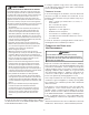
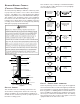
To rotate the induced draft blower clockwise, you will need
to purchase one (0270F01119) chimney transition bottom kit.
1. Disconnect electrical power from the furnace.
2. Disconnect the induced draft blower power leads, fl ue
pipe, and pressure switch tubing.
3. Remove the round cutout from the right side of the
wrapper.
4. Remove and save the four screws that fasten the
induced draft blower to the fl ue collector box.
5. Remove and save the three screws that hold the
chimney assembly to the induced draft blower.
6. Remove and save the four screws that fasten the
chimney top to the chimney bottom.
7. Remove the chimney transition bottom from the
transition bottom kit.
8. Install the chimney top with the four screws retained
from step 6 onto the new chimney transition bottom
from the transition bottom kit.
9. Install chimney assembly with the three screws retained
from step 5 onto the induced draft blower.
10. Reinstall the induced draft blower rotating it 90 degrees
clockwise from the original upfl ow confi guration using
the four screws retained in step 3. Ensure the gasket
located between the induced draft blower and the
collector box is rotated accordingly.
11. Reconnect the induced draft blower power leads.
NOTE: If the wires are not long enough, pull extra wire
from the wire bundle in the blower compartment.
12. Reconnect the fl ue pipe, and the pressure switch tubing.
Ensure that all wires and the pressure switch tubing is
at least one inch from the fl ue pipe, or any other hot
surface.
13. Restore power to furnace.
Counterfl ow units are shipped with the induced draft blower
discharging from the top of the furnace. (“Top” as viewed for
a counterfl ow installation.)
Vent the furnace in accordance with the National Fuel Gas
Code NFPA54/ANSI Z223.1-latest edition.
N
EVER
ALLOW
THE
PRODUCTS
OF
COMBUSTION
,
INCLUDING
CARBON
MONOXIDE
,
TO
ENTER
THE
RETURN
DUCTWORK
OR
CIRCULATION
AIR
SUPPLY
.
WARNING