
Installation Guide


34
FLAME S ENSOR (QUALIFIED S ERVICER O NLY)
Under some conditions, the fuel or air supply can create a
nearly invisible coating on the flame sensor. This coating acts
as an insulator causing a drop in the flame sense signal. If the
flame sense signal drops too low the furnace will not sense
flame and will lock out. The flame sensor should be carefully
cleaned by a qualified servicer using emery cloth or steel wool.
Following cleaning, the flame sense signal should be 1 to 6
microamps at 115 volts.
IGNITER (QUALIFIED SERVICER O NLY)
If the igniter and the surrounding air are at about 70°F and the
igniter wires are not connected to any other electrical compo-
nents, the resistance of the igniter should not exceed 75 ohms.
If it does, the igniter should be replaced.
BURNERS
T
O
PREVENT
PERSONAL
INJURY
OR
DEATH
,
DO
NOT
REMOVE
ANY
INTERNAL
COMPARTMENT
COVERS
OR
ATTEMPT
ANY
ADJUSTMENT
.
E
LECTRICAL
COMPONENTS
ARE
CONTAINED
IN
BOTH
COMPARTMENTS
.
C
ONTACT
A
QUALIFIED
SERVICE
AGENT
AT
ONCE
IF
AN
ABNORMAL
FLAME
APPEARANCE
SHOULD
DEVELOP
.
WARNING
Periodically during the heating season, make a visual check of
the burner flames. Turn the furnace on at the thermostat. Wait
a few minutes, since any dislodged dust will alter the normal
flame appearance. Flames should be stable, quiet, soft and
blue with slightly orange tips. They should not be yellow. They
should extend directly outward from the burner ports without
curling downward, floating or lifting off the ports.
C
LEANING
(Q
UALIFIED
S
ERVICER
O
NLY
)
1. Shut off electric power and gas supply to the furnace.
2. Disconnect the rollout limit wires, flame sensor wire, and
disconnect the igniter plug.
L
ABEL
ALL
WIRES
PRIOR
TO
DISCONNECTION
WHEN
SERVICING
CONTROLS
. W
IRING
ERRORS
CAN
CAUSE
IMPROPER
AND
DANGEROUS
OPERATION
. V
ERIFY
PROPER
OPERATION
AFTER
SERVICING
.
CAUTION
3. Remove four (4) screws securing the burner box top.
T
HE
IGNITER
IS
FRAGILE
AND
CAN
BE
EASILY
DAMAGED
. U
SE
EXTREME
CAUTION
WHEN
REMOVING
THE
BURNER
BOX
TOP
.
CAUTION
4. Remove the screws securing the burners to the burner
bracket. Remove the burners.
5. Use bottle brush to clean burner insert and inside of
burner.
6. Replace burner (opposite of removal). Ensure burners
are fully seated on burner bracket and are properly
aligned. Replace burner box top. Reconnect wiring.
7. Turn on electric power and gas supply to the furnace.
8. Check furnace for proper operation. Refer to “Operational
Checks” section to verify burner flame characteristics.
B
EFORE
L
EAVING
AN
I
NSTALLATION
• Cycle the furnace with the thermostat at least three
times. Verify cooling and fan only operation.
• Review the Owner’s Manual with the homeowner and
discuss proper furnace operation and maintenance.
• Leave literature packet near furnace.
R
EPAIR
AND
R
EPLACEMENT
P
ARTS
• When ordering any of the listed functional parts, be sure
to provide the furnace model, manufacturing, and serial
numbers with the order.
• Although only functional parts are shown in the parts
list, all sheet metal parts, doors, etc. may be ordered by
description.
• Parts are available from your distributor.
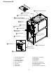
Functional Parts List-
Gas Valve Blower/Collector Box Gasket
Natural Gas Orifice Primary Limit Switch
Propane Gas Orifice Rollout Limit Switch
Burner Auxiliary Limit Switch
Hot Surface Igniter Heat Exchanger
Flame Sensor Door Switch
Gas Manifold Transformer
Ignition Control Blower Wheel
Blower Mounting Bracket Blower Housing
Pressure Switch Blower Cutoff
Pressure Switch Hose Blower Motor
Induced Draft Blower Motor Mount Bracket
Collector Box Capacitor