
GMS8 Installation Manual

11
T
O
PREVENT
POSSIBLE
PERSONAL
INJURY
OR
DEATH
DUE
TO
ASPHYXIATION
,
COM M ON
VENTING
W ITH
OTHER
M ANUFACTURER
’
S
INDUCED
DRAFT
APPLIANCES
IS
NOT
ALLOW ED
.
WARNING
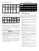
The minimum vent diameter for the Category I venting system is as
shown:
UPFLOW COUNTERFLOW
40 4 Inch 4 Inch
60 4 Inch 4 Inch
80 4 Inch 4 Inch
100 5 Inch 5 Inch
120 5 Inch N/A
140 5 Inch N/A
MODEL
MINIMUM VENT
Under some conditions, larger vents than those shown above may
be required or allowed. When an exist ing furnace is removed from
a venting syst em serving other appliances, the venting system may
be too large to properly vent the remaining attached appliances.
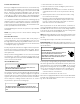
Upflow or Horizontal units are shipped with the induced draft
blower discharging from the top of the furnace. (“ Top” is as viewed
for an upflow installation.) The induced draft blower can be ro-
tated 90 degrees with the (0270F01119) chimney transition bot-
tom kit for Category I venting. For upflow models installed verti-
cally or horizontally, a four inch single wall pipe can be used to
extend the induced draft blower outlet 1/2” beyond the furnace
cabinet. THIS PRODUCT IS NOT DESIGNED FOR COUNTERCLOCK-
W ISE INDUCED DRAFT BLOW ER ROTATION.
Vent the furnace in accordance with the National Fuel Gas Code
NFPA 54/ANSI Z223.1 - latest edition.
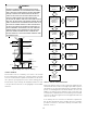
Venting - Furnace Installed in Horizontal Position
THIS FURNACE IS NOT DESIGN CERTIFIED TO BE HORIZONTALLY
VENTED THROUGH AN EXTERIOR SIDE WALL.
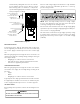
The following describes an optional venting procedure when the
furnace is installed in the horizontal left discharge position.
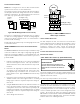
To rotate the induced draft blower clockwise, you will need to
purchase one (0270F01119) chimney transition bottom kit.
1. Disconnect electrical power from the furnace.
2. Disconnect the induced draft blower power leads, flue pipe,
and pressure switch tubing.
3. Remove the round cutout from the right side of the wrapper.
4. Remove and save the four screws that fasten the induced
draft blower to the flue collector box.
5. Remove and save the three screws that hold the chimney
assembly to the induced draft blower.
6. Remove and save the four screws that fasten the chimney
top to the chimney bottom.
7. Remove the chimney transition bottom from the transition
bottom kit.
8. Install the chimney top with the four screws retained from
step 6 onto the new chimney transition bottom from the
transition bottom kit.
9. Remove the induced draft blower and install the new
chimney assembly to it using the three screws retained
from step 5.
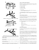
10. Rotate the induced draft blower 90 degrees to the right,
feed the flue pipe through the round cutout from the outside
of the wrapper, and fit onto the chimney top assembly.
Secure the pipe to the chimney top from the front, top, and
bottom using (3) screws and rotating the induced draft
blower to properly orient the assembly. NOTE: If the pipe
section is less than 18”, then attach it directly to the chimney
top on 3 sides and feed it through the round cutout from the
inside of the wrapper.
11. Reattach the induced draft blower using the (4) screws
retained from step 3. Ensure the gasket located between
the induced draft blower and collector box is rotated
accordingly.
12. Reconnect the induced draft blower power leads. NOTE: If
the wires are not long enough, pull extra wire from the wire
bundle in the blower compartment.
13. Reconnect the remaining flue pipe, and the pressure switch
tubing. Ensure that all wires and the pressure switch tubing
is at least one inch from the flue pipe, or any other hot
surface.
14. Restore power to furnace.
NOTE: In a horizontal installation the air conditioning coil must
be adequately supported by proper brackets and supports.
Inadequate coil support can result in furnace cabinet distortion
and air leakage.
Counterflow units are shipped with the induced draft blower dis-
charging from the top of the furnace. (“ Top” as viewed for a coun-
terflow installation.)
Vent the furnace in accordance with the National Fuel Gas Code
NFPA54/ ANSI Z223.1-latest edition.
N
EVER
ALLOW
THE
PRODUCTS
OF
COM BUSTION
,
INCLUDING
CARBON
M ONOXIDE
,
TO
ENTER
THE
RETURN
DUCTW ORK
OR
CIRCULATION
AIR
SUPPLY
.
WARNING
EXTERIOR M ASONRY CHIM NEYS (CATEGORY I FURNACES ONLY)
An exterior masonry chimney is defined as a “ M asonry” chimney
exposed to the outdoors on one or more sides below the roof
line.” The ability to use a clay lined masonry chimney depends
on a parameter not associated with interior chimneys. This vari-
able is the geographic location of the installation. Researchers
have discovered that the winter design temperatures have a di-
rect impact on the suitability of this type of venting. In most
situations, the existing masonry chimneys will require a properly
sized metallic liner.