
GMS8 Installation Manual

27
Natural Gas Minimum: 4.5" w.c. Maximum: 10.0" w.c.
Propane Gas Minimum: 11.0" w.c. Maximum: 13.0" w.c.
INLET GAS SUPPLY PRESSURE
If supply pressure differs from table, make the necessary adjust-
ments to pressure regulator, gas piping size, etc., and/or consult
with local gas utility.
5. Turn OFF gas to furnace at the manual shutoff valve and
disconnect manometer. Reinstall plug before turning on
gas to furnace.
6. Turn OFF any unnecessary gas appliances stated in step 3.
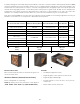
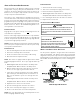
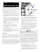
Gas Line
Gas
Shutoff
Valve
Gas Line
To Furn ac e
Drip Leg Cap
With Fitting
Manometer Hose
Measuring Inlet Gas Pressure (Alt. Method)
GAS M ANIFOLD PRESSURE M EASUREM ENT AND ADJUSTM ENT
T
O
PREVENT
UNRELIABLE
OPERATION
OR
EQUIPM ENT
DAM AGE
,
THE
GAS
M ANIFOLD
PRESSURE
M UST
BE
AS
SPECIFIED
ON
THE
UNIT
RATING
PLATE
. O
NLY
M INOR
ADJUSTM ENTS
SHOULD
BE
M ADE
BY
ADJUSTING
THE
GAS
VALVE
PRESSURE
REGULATOR
.
CAUTION
HIGH VOLTAGE !
D
ISCONNECT
ALL
POW ER
BEFORE
SERVICING
OR
INSTALLING
THIS
UNIT
. M
ULTIPLE
POW ER
SOURCES
M AY
BE
PRESENT
. F
AILURE
TO
DO
SO
M AY
CAUSE
PROPERTY
DAM AGE
,
PERSONAL
INJURY
OR
DEATH
.
WARNING
MODELS USING SINGLE STAGE GAS VALVES
This valve is shipped from the factory with the regulator preset
(see control label).
Consult the appliance rating plate to ensure burner manifold pres-
sure is as specified. If another outlet pressure is required, follow
these steps.
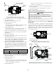
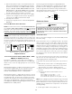
Gas Valve On/Off
Selector Switch
Regulator
Vent
High Fire
Regulator
Adjust
Low Fire
Regulator
Adjust
Honeywell Model VR9205 (Two-Stage)
i
M
a
n
o
m
e
t
e
r
M
a
n
o
m
e
t
e
r
H
o
s
e
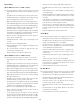
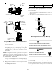
Common
Terminal(C)
High Fire Coil
Terminal (HI)
Low Fire Coil
Terminal (LO)
Inlet Pressure Tap
1/8 NPT
O
p
e
n
t
o
A
t
m
o
s
p
h
e
r
e
Outlet Pressure Tap
1/8 NPT
Honeywell Model VR9205 Connected to Manometer
1. Turn OFF gas to furnace at the manual gas shutoff valve
external to the furnace.
2. Connect a calibrated water manometer (or appropriate gas
pressure gauge) at either the gas valve inlet pressure Tap
or the gas piping drip leg. See Honeywell gas valve figure
or White-Rodgers gas valve figure for location of inlet
pressure Tap.
NOTE: If measuring gas pressure at the drip leg or Honeywell gas
valve, a field-supplied hose barb fitting must be installed prior to
making the hose connection. If using the inlet pressure Tap on the
White-Rodgers gas valve, then use the 36G/ J Valve Pressure Check
Kit, Goodman Part No. 0151K00000S.
3. Turn ON the gas supply and operate the furnace and all
other gas consuming appliances on the same gas supply
line.
4. M easure furnace gas supply pressure with burners firing.
Supply pressure must be within the range specified in the
Inlet Gas Supply Pressure table.