
GMS8 Installation Manual

28
1. Turn OFF gas to furnace at the manual gas shutoff valve
external to the furnace.
2. Turn OFF all electrical power to the system.
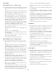
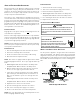
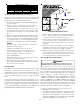
3. Outlet pressure tap connections:
a. Honeywell valve:
Remove the outlet pressure Tap plug. Install an 1/8” NPT
hose barb fitting into the outlet pressure tap.
b. White-Rodgers valve:
Back outlet pressure test screw (outlet pressure Tap) out
one turn (counterclockwise, not more than one turn).
4. Attach a hose and manometer to the outlet pressure barb
fitting (Honeywell valve) or outlet pressure Tap (White-
Rodgers valve).
5. Turn ON the gas supply.
6. Turn ON power and close thermostat “R” and “ W” contacts
to provide a call for heat.
7. Using a leak detection solution or soap suds, check for
leaks at outlet pressure Tap plug (Honeywell valve) or screw
(White-Rodgers valve). Bubbles forming indicate a leak.
SHUT OFF GAS AND REPAIR ALL LEAKS IM MEDIATELY!
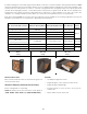
8. Measure the gas manifold pressure with burners firing.
Adjust manifold pressure using the following M anifold Gas
Pressure table.
Natur al Gas 3.2" - 3.8 " w.c.
Propane Gas 9.7" - 10.3" w.c.
M anifold Gas Pre ssure
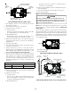
9. Remove regulator cover screw from the outlet pressure
regulator and turn screw clockwise to increase pressure or
counterclockwise to decrease pressure. Replace regulator
cover screw.
10. Turn OFF all electrical power and gas supply to the system.
11. Remove the manometer hose from the hose barb fitting
or outlet pressure Tap.
12. Replace outlet pressure tap:
a. Honeywell valve:
Remove the 1/8” NPT hose barb fitting from the outlet
pressure tap. Replace the outlet pressure boss plug and
seal with a high quality thread sealer.
b. White-Rodgers valve: Turn outlet pressure test screw in
to seal pressure port (clockwise, 7 in-lb minimum).
13. Turn ON electrical power and gas supply to the system.
14. Close thermostat contacts to provide a call for heat.
15. Retest for leaks. If bubbles form, SHUT OFF GAS AND REPAIR
ALL LEAKS IM MEDIATELY!
MODELS USING TWO STAGE GAS VALVES
T
O
PREVENT
UNRELIABLE
OPERATION
OR
EQUIPM ENT
DAM AGE
,
THE
GAS
M ANIFOLD
PRESSURE
M UST
BE
AS
SPECIFIED
ON
THE
UNIT
RATING
PLATE
. O
NLY
M INOR
ADJUSTM ENTS
SHOULD
BE
M ADE
BY
ADJUSTING
THE
GAS
VALVE
PRESSURE
REGULATOR
.
CAUTION
Only small variations in gas pressure should be made by adjust-
ing the gas valve pressure regulator. The manifold pressure must
be measured with the burners operating. To measure and adjust
the manifold pressure, use the following procedure.
1. Turn OFF gas to furnace at the manual gas shutoff valve
external to the furnace.
2. Turn off all electrical power to the system.
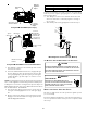
3. Outlet pressure tap connections:
a. Honeywell valve: Remove the outlet pressure Tap plug.
Install an 1/8" NPT hose barb fitting into the outlet
pressure tap.
b. White-Rodgers valve: Back outlet pressure test screw
(inlet/outlet pressure Tap) out one turn
(counterclockwise, not more than one turn).
4. Attach a hose and manometer to the outlet pressure barb
fitting (Honeywell valve) or outlet pressure Tap (White-
Rodgers valve).
5. Turn ON the gas supply.
6. Turn on power and close thermostat “ R” and “ W1” contacts
to provide a call for low stage heat.
7. M easure the gas manifold pressure with burners firing.
Adjust manifold pressure using the M anifold Gas Pressure
table shown below.
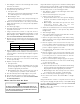
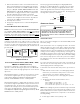
8. Remove regulator cover screw from the low (LO) outlet
pressure regulator adjust tower and turn screw clockwise
to increase pressure or counterclockwise to decrease
pressure. Replace regulator cover screw.
9. Close thermostat “R” and “W2” contacts to provide a call
for high stage heat.
10. Remove regulator cover screw from the high (HI) outlet
pressure regulator adjust tower and turn screw clockwise
to increase pressure or counterclockwise to decrease
pressure. Replace regulator cover screw.
11. Turn off all electrical power and gas supply to the system.
12. Remove the manometer hose from the hose barb fitting
or outlet pressure Tap.
13. Replace outlet pressure tap:
a. Honeywell valve: Remove the 1/8" NPT hose barb fitting
from the outlet pressure tap. Replace the outlet pressure
Tap plug and seal with a high quality thread sealer.
b. White-Rodgers valve: Turn outlet pressure test screw in
to seal pressure port (clockwise, 7 in-lb minimum).
14. Turn on electrical power and gas supply to the system.
15. Close thermostat contacts “ R” and “ W1/ W2” to energize
the valve.
Using a leak detection solution or soap suds, check for leaks a t
outlet pressure Tap plug (Honeywell valve) or screw (White-Rodg-
ers valve). Bubbles forming indicate a leak. SHUT OFF GAS AND
REPAIR ALL LEAKS IM MEDIATELY!
NOTE: For gas to gas conversion, consult your dealer for
appropriate conversion.