
GMS8 Service Manual
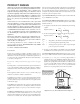
PRODUCT DESIGN
29
High altitude kits are purchased according to the installa-
tion altitude and usage of either natural or propane gas. Refer
to the product Specification Sheet or Technical Manual for a
tabular listing of appropriate altitude ranges and correspond-
ing manufacturer’s high altitude (Natural, Propane gas, and/
or Pressure Switch) kits.
Do not derate the furnace by adjusting the manifold pres-
sure to a lower pressure than specified on the furnace rating
plate. The combination of the lower air density and a lower
manifold pressure will prohibit the burner orifice from draw-
ing the proper amount of air into the burner. This may cause
incomplete combustion, flashback, and possible yellow tip-
ping.
In some areas the gas supplier may artificially derate the
gas in an effort to compensate for the effects of altitude. If
the gas is artificially derated, the appropriate orifice size
must be determined based upon the BTU/ft
3
content of the
derated gas and the altitude. Refer to the National Fuel Gas
Code, NFPA 54/ANSI Z223.1, and information provided by
the gas supplier to determine the proper orifice size.
A different pressure switch may be required at high altitude
regardless of the BTU/ft
3
content of the fuel used. Refer to
the product Specification Sheet or Technical Manual for a
tabular listing of appropriate altitude ranges and correspond-
ing manufacturer’s pressure switch kits.
PROPANE GAS CONVERSION
WARNING
P
OSSIBLE PROPERTY DAMAGE, PERSONAL INJURY OR DEATH MAY OCCUR IF
THE CORRECT CONVERSION KITS ARE NOT INSTALLED.
T
HE APPROPRIATE KITS
MUST BE APPLIED TO INSURE SAFE AND PROPER FURNACE OPERATION.
A
LL
CONVERSIONS MUST BE PERFORMED BY A QUALIFIED INSTALLER OR SERVICE
AGENCY.
This unit is configured for natural gas. The appropriate
manufacturer’s propane gas conversion kit, must be applied
for propane gas installations.
• Single-stage 80% furnace modelsusing a Honeywell
VR8215 single stage valve or a White-Rodgers 36J22
use LPT-03 LP Conversion Kit.
Refer to the specification sheet for the model you are servic-
ing. Refer to the “propane gas and/or High Altitude Installa-
tions” section for details.
GAS VALVE
This unit is equipped with a 24 volt gas valve controlled dur-
ing furnace operation by the integrated control module. As
shipped, the valve is configured for natural gas. The valve is
field convertible for use with propane gas by using the ap-
propriate propane gas conversion kit. Taps for measuring
the gas supply pressure and manifold pressure are provided
on the valve.
NOTE: The gas supply pressure on White-Rodger "J"
model gas valve, used on single stage furnaces, can
be checked with a gas pressure test kit (Part
#0151K00000S) available through our authorized dis-
tributors.
The gas valve has a manual ON/OFF control located on the
valve itself. This control may be set only to the “ON” or “OFF”
position. Refer to the Lighting Instructions Label or the “Put-
ting the Furnace Into Operation” section of this manual or
the installation instructions for use of this control during start
up and shut down periods.
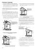
GAS PIPING CONNECTIONS
CAUTION
T
O AVOID POSSIBLE UNSATISFACTORY OPERATION OR EQUIPMENT DAMAGE
DUE TO UNDERFIRING OF EQUIPMENT, USE THE PROPER SIZE OF
NATURAL/PROPANE GAS PIPING NEEDED WHEN RUNNING PIPE FROM THE
METER/TANK TO THE FURNACE.
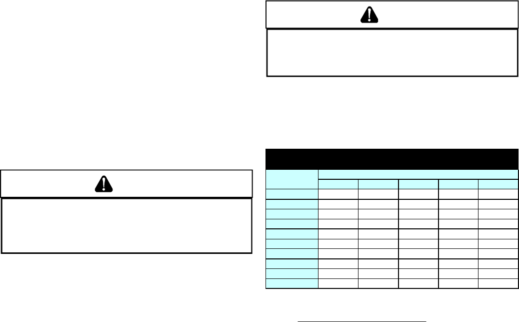
The gas piping supplying the furnace must be properly sized
based on the gas flow required, specific gravity of the gas,
and length of the run. The gas line installation must comply
with local codes, or in their absence, with the latest edition
of the National Fuel Gas Code, NFPA 54/ANSI Z223.1.
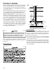
Length of Nominal Black Pipe Size
Pipe in Feet 1/2" 3/4" 1" 1 1/4" 1 1/2"
10 132 278 520 1050 1600
20 92 190 350 730 1100
30 73 152 285 590 980
40 63 130 245 500 760
50 56 115 215 440 670
60 50 105 195 400 610
70 46 96 180 370 560
80 43 90 170 350 530
90 40 84 160 320 490
100 38 79 150 305 460
CFH =
(Pressure 0.5 psig or less and pressure drop of 0.3" W.C.; Based on 0.60 Specific
Gravity Gas)
Natural Gas Capacity of Pipe
In Cubic Feet of Gas Per Hour (CFH)
BTUH Furnace Input
Heating Value of Gas (BTU/Cubic Foot)
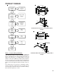
To connect the furnace to the building’s gas piping, the in-
staller must supply a ground joint union, drip leg, manual
shutoff valve, and line and fittings to connect to gas valve. In
some cases, the installer may also need to supply a transi-
tion piece from 1/2" pipe to a larger pipe size.
The following stipulations apply when connecting gas pip-
ing. Refer to the following figures for typical gas line connec-
tions to the furnace.
1. Use black iron or steel pipe and fittings for the building
piping.
2. Use pipe joint compound on male threads only. Pipe
joint compound must be resistant to the action of the
fuel used.