
GMS8 Service Manual
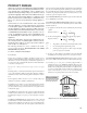
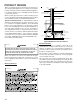

PRODUCT DESIGN
30
3. Use ground joint unions.
4. Install a drip leg to trap dirt and moisture before it can
enter the gas valve. The drip leg must be a minimum
of three inches long.
5. Install a 1/8" NPT pipe plug fitting, accessible for test
gage connection, immediately upstream of the gas
supply connection to the furnace.
6. Use two pipe wrenches when making connection to
the gas valve to keep it from turning. The orientation
of the gas valve on the manifold must be maintained
as shipped from the factory.
7. Install a manual shutoff valve between the gas meter
and unit within six feet of the unit. If a union is in-
stalled, the union must be downstream of the manual
shutoff valve, between the shutoff valve and the fur-
nace.
8. Tighten all joints securely.
9. Connect the furnace to the building piping by one of
the following methods:
– Rigid metallic pipe and fittings.
– Semi-rigid metallic tubing and metallic fittings. Alu-
minum alloy tubing must not be used in exterior loca-
tions. In order to seal the grommet cabinet penetra-
tion, rigid pipe must be used to reach the outside
of the cabinet. A semi-rigid connector to
the gas piping may be used from there.
10. Use listed gas appliance connectors in accordance with
their instructions. Connectors must be fully in the same
room as the furnace.
11. Protect connectors and semi-rigid tubing against physi-
cal and thermal damage when installed. Ensure alumi-
num-alloy tubing and connectors are coated to protect
against external corrosion when in contact with masonry,
plaster, or insulation, or subjected to repeated wetting
by liquids such as water (except rain water), detergents,
or sewage.
CAUTION
E
DGES OF SHEET METAL HOLES MAY BE SHARP.
U
SE GLOVES A PRECAUTION
WHEN REMOVING HOLE PLUGS.
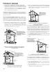
DIRECT/STANDARD INLET PIPING
When gas piping enters directly to the gas valve through
the standard inlet hole (upflow through the right side panel),
the installer must supply straight pipe with a ground joint
union to reach the exterior of the furnace. NOTE: The rigid
pipe must be long enough to reach the outside of the cabi-
net to seal the grommet cabinet penetration on 90% fur-
naces. A semi-rigid connector to the gas piping can be
used outside the cabinet per local codes.
INDIRECT/ALTERNATE INLET PIPING
When gas piping enters indirectly to the gas valve through
the alternate gas inlet hole the installer must supply the
following fittings (starting from the gas valve) to reach the
outside of the cabinet (NOTE: On the 90% furnaces the
installer must swap the alternate inlet hole plug with the
standard inlet grommet in order to seal the cabinet):
• Coupling.
• 90 degree elbow.
• 2 inch close nipple.
• 90 degree elbow.
• Straight pipe, with a ground joint union, to reach the
exterior of the furnace. NOTE: A semi-rigid connec-
tor to the gas piping can be used outside the cabinet
per local codes.
GAS PIPING CHECKS
Before placing unit in operation, leak test the unit and gas
connections.
WARNING
T
O AVOID THE POSSIBLITY OF EXPLOSION OR FIRE, NEVER USE A MATCH
OR OPEN FLAME TO TEST FOR LEAKS.
Check for leaks using an approved chloride-free soap and
water solution, an electronic combustible gas detector, or
other approved testing methods.
NOTE: Never exceed specified pressures for testing. Higher
pressure may damage the gas valve and cause subsequent
overfiring, resulting in heat exchanger failure. Disconnect
this unit and shutoff valve from the gas supply piping sys-
tem before pressure testing the supply piping system with
pressures in excess of 1/2 psig (3.48 kPa). Isolate this unit
from the gas supply piping system by closing its external
manual gas shutoff valve before pressure testing supply
piping system with test pressures equal to or less than 1/2
psig (3.48 kPa).
PROPANE GAS TANKS AND PIPING
WARNING
P
ROPANE GAS IS HEAVIER THAN AIR AND ANY LEAKING GAS CAN SETTLE IN
ANY LOW AREAS OR CONFINED SPACES.
T
O PREVENT PROPERTY DAMAGE,
PERSONAL INJURY, OR DEATH DUE TO FIRE OR EXPLOSION CAUSED BY A
PROPANE GAS LEAK, INSTALL A GAS DETECTION WARNING DEVICE.
A gas detecting warning system is the only reliable way to
detect a propane gas leak. Iron oxide (rust) can reduce the
level of odorant in propane gas. Do not rely on your sense
of smell. Contact a local propane gas supplier about install-
ing a gas detecting warning system. If the presence of gas
is suspected, follow the instructions on this page.
All propane gas equipment must conform to the safety stan-
dards of the National Board of Fire Underwriters, NBFU
Manual 58.