
GMS8 Service Manual


PRODUCT DESIGN
33
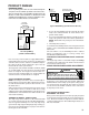
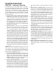
HUMIDIFIER WIRING
Accessory wiring connections are to be made through the
1/4" quick connect terminals provided on the furnace inte-
grated control module. The Humidifier and Electronic Air
Cleaner hot and neutral terminals are identified as HUM
and EAC. All field wiring must conform to applicable codes.
Connections should be made as shown below.
ELECTRONIC
AIR CLEANER
HUMIDIFIER
OPTIONAL
ACCESORIES
12 PIN
CONNECTOR
120 VAC
NEUTRAL
TERMINALS
N
E
U
T
R
A
L
HUM-H
EAC-H
120 VAC
HOT AND
PARK
TERMINALS
INTEGRATED
CONTROL
MODULE
Accessory Wiring
(certain control boards)
If it is necessary for the installer to supply additional line
voltage wiring to the inside of the furnace, the wiring must
conform to all local codes, and have a minimum tempera-
ture rating of 105°C. All line voltage wire splices must be
made inside the furnace junction box.
The integrated control module humidifier terminals (HUM)
are energized with 115 volts whenever the induced draft
blower is energized. The integrated control module elec-
tronic air cleaner terminals (EAC) are energized with 115
volts whenever the circulator blower is energized.
24 VOLT THERMOSTAT WIRING
NOTE: Low voltage connections can be made through ei-
ther the right or left side panel. Wire routing must not inter-
fere with circulator blower operation, filter removal, or rou-
tine maintenance.
A 40 V.A. transformer and an integrated electronic control
are built into the furnace to allow use with most cooling
equipment. Consult the wiring diagram, located in the Tech-
nical Manual or on the blower door for further details of 115
Volt and 24 Volt wiring.
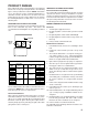
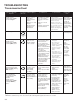
THERMOSTAT WIRING - SINGLE-STAGE
The single stage furnace will have a "W" terminal and will
use a single stage thermostat. The following drawing illus-
trates the typical field wiring for a heat only single stage
system and a single stage heating/single stage cooling sys-
tem. Refer to the following figures for proper connections to
the integrated control module.
Furnace
Control
Furnace
Control
Remote
Condensing
Unit
Heating
Room
Thermostat
Heating/Cooling
Room Thermostat
WW
Typical Field Wiring (24 VAC Control Circuit)
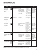
1. Secure the dehumidistat hot wire (typically the black
lead) to the terminal marked “R” on the furnace inte-
grated control module.
2. Secure the dehumidistat ground wire (typically the green
lead) to the ground screw on the furnace junction box.
NOTE: Ground wire may not be present on all dehumi-
distats.
3. Turn ON power to furnace.
To enable the dehumidify function on the integrated control
module, set the dehumidification ENABLE dipswitch from
OFF to ON.
Once the switch is set, the dehumidify function is enabled
during a combination call for cooling (T-Stat) and
dehumidication (DEHUM-Stat).
CONTINUOUS FAN OPERATION SINGLE STAGE FUR-
NACES
The single stage furnace control will energize the heating
circulator fan speed when the fan switch on the thermostat
is turned to the "ON" position.
CIRCULATOR BLOWER SPEED ADJUSTMENT
WARNING
HIGH VOLTAGE
D
ISCONNECT
ALL
POWER BEFOR CHANGING SPEED TAPS.
MULTIPLE POWER SOURCES MAY BE PRESENT. FAILURE TO DO
SO MAY CAUSE PROPERTY DAMAGE, PERSONAL INJURY OR DEATH.
Connect the correct motor leads to the COOL, HEAT, and
PARK terminals. If the heating speed equals cooling speed,
use the jumper wire provided. All unused motor leads that
are not connected to "PARK" terminals on the control must
be taped to prevent shorts.
CIRCULATING AIR AND FILTERS
DUCTWORK - AIR FLOW
Duct systems and register sizes must be properly designed
for the C.F.M. and external static pressure rating of the fur-
nace. Ductwork should be designed in accordance with the
recommended methods of "Air Conditioning Contractors of
America" manual D.