
Installation Guide


9
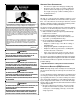
Top - 1"
Side
Clearance - 1"
Back - 0"
Front Clearance - 3"
V
ent Pipe Clearance to Combustibles-
6" using Single Wall Connector or 1"
using B-1 vent.
• Adequate combustion/ventilation air must be supplied
to the closet.
• Furnace must be completely sealed to floor or base.
Combustion/ ventilation air supply pipes must
terminate 12" from top of closet and 12" from floor of
closet. DO NOT remove solid base plate for side
return.
• Return air ducts must be completely sealed to the
furnace and terminate outside the enclosure surfaces.
CLEARANCES AND A CCESSIBILITY
Unobstructed front clearance of 24" for servicing is recom-
mended.
TOP
B1-VENT SINGLE
(PLENUM)
1" 6" 1" 3" 0" 1"
VENT
SIDES FRONT BACK
Top clearance for horizontal configuration - 1"
INSTALLATION P OSITIONS
An upflow furnace may be installed in an upright position or
horizontal on either the left or right side panel. Do not install
this furnace on its back. For vertically installed upflow furnaces,
return air ductwork may be attached to the side panel(s) and/
or basepan. For horizontally installed upflow furnaces, return
air ductwork must be attached to the basepan. For counterflow
furnaces, return ductwork must be attached to the top end of
the blower compartment.
NOTE: Ductwork must never be attached to the back of the
furnace.
• If the furnace is used in connection with a cooling unit,
install the furnace upstream or in parallel with the
cooling unit coil. Premature heat exchanger failure
will result if the cooling unit coil is placed ahead of the
furnace.
For vertical (upflow or downflow) applications, the
minimum cooling coil width shall not be less than
furnace width minus 1”. Additionally, a coil installed
above an upflow furnace or under a counterflow furnace
may be the same width as the furnace or may be one
size larger than the furnace. Example: a “C” width coil
may be installed with a “B” width furnace.
For upflow applications, the front of the coil and furnace
must face the same direction.
• If the furnace is installed in a residential garage,
position the furnace so that the burners and ignition
source are located not less than 18 inches (457 mm)
above the floor. Protect the furnace from physical
damage by vehicles.
• If the furnace is installed horizontally, the furnace
access doors must be vertical so that the burners fire
horizontally into the heat exchanger. Do not install
the unit with the access doors on the “up/top” or “down/
bottom” side of the furnace.
• Do not connect this furnace to a chimney flue that
serves a separate appliance designed to burn solid
fuel.
• For counterflow installations, the air conditioning coil
must be downstream from the heat exchanger of the
furnace.
• Counterflow installation over a noncombustible floor.
Before setting the furnace over the plenum opening,
ensure the surface around the opening is smooth and
level. A tight seal should be made between the furnace
base and floor by using a silicon rubber caulking
compound or cement grout.
• Counterflow installation over a combustible floor. If
installation over a combustible floor becomes
necessary, use an accessory subbase (see
Specification Sheet applicable to your model for details).
A special accessory subbase must be used for upright
counterflow unit installations over any combustible
material including wood. Follow the instructions with
the subbase for proper installations. Do not install the
furnace directly on carpeting, tile, or other combustible
material other than wood flooring. (NOTE: The subbase
will not be required if an air conditioning coil is installed
between the supply air opening on the furnace and the
floor.