INSTALLATION INSTRUCTIONS FOR *(D, M)VC8 GAS FURNACE (CATEGORY I ) Installer: Affix all manuals adjacent to the unit. These furnaces comply with requirements embodied in the American National Standard / National Standard of Canada ANSI Z21.47·CSA2.3 Gas Fired Central Furnaces. RECOGNIZE THIS SYMBOL AS A SAFETY PRECAUTION. ATTENTION INSTALLING PERSONNEL As a professional installer, you have an obligation to know the product better than the customer.
Table of Contents SAFETY CONSIDERATIONS ........................................................................................................................................................... 4 ADDITIONAL SAFETY CONSIDERATIONS ................................................................................................................................... 5 SHIPPING INSPECTION ...............................................................................................................................
Table of Contents START-UP PROCEDURE AND ADJUSTMENT ................................................................................................................................... 24 HEAT ANTICIPATOR SETTING ............................................................................................................................................... 24 FURNACE OPERATION .......................................................................................................................................
SAFETY CONSIDERATIONS WARNING IF THE INFORMATION IN THESE INSTRUCTIONS IS NOT FOLLOWED EXACTLY, A FIRE OR EXPLOSION MAY RESULT CAUSING PROPERTY DAMAGE , PERSONAL INJURY OR LOSS OF LIFE. DO NOT STORE OR USE GASOLINE OR OTHER FLAMMABLE VAPORS AND LIQUIDS IN THE VICINITY OF THIS OR ANY OTHER APPLIANCE . WHAT TO DO IF YOU SMELL GAS: D O NOT TRY TO LIGHT ANY APPLIANCE. D O NOT TOUCH ANY ELECTRICAL SWITCH; DO NOT USE ANY PHONE IN YOUR BUILDING . IMMEDIATELY CALL YOUR GAS SUPPLIER FROM A NEIGHBOR’ S PHONE.
WARNING TO PREVENT PERSONAL INJURY OR DEATH DUE TO ASPHYXIATION, THIS FURNACE MUST BE CATEGORY I VENTED. DO NOT VENT USING CATEGORY III VENTING. PROVISIONS MUST BE MADE FOR VENTING COMBUSTION PRODUCTS OUTDOORS THROUGH A PROPER VENTING SYSTEM . THE LENGTH OF FLUE PIPE COULD BE A LIMITING FACTOR IN LOCATING THE FURNACE.
ELECTROSTATIC DISCHARGE (ESD) PRECAUTIONS This product may also be installed with the ComfortNet thermostat and a non-ComfortNet compatible single stage air conNOTE: Discharge body’s static electricity before touching unit. ditioning unit. However, this reduces the benefits of the An electrostatic discharge can adversely affect electrical com- ComfortNet system as the enhancements will only apply to the ponents. furnace.
• The furnace heat exchanger, components, duct system, air filters and evaporator coils are thoroughly cleaned following final construction clean up. All furnace operating conditions (including ignition, input rate, temperature rise and venting) are verified according to these installation instructions. In the USA, this furnace MUST be installed in accordance with the latest edition of the ANSI Z223.
• • • • • • Ensure the temperature of the return air entering the furnace is between 55°F and 100°F when the furnace is heating. Provisions must be made for venting combustion products outdoors through a proper venting system. The length of flue pipe could be a limiting factor in locating the furnace. Ensure adequate combustion air is available for the furnace. Improper or insufficient combustion air can expose building occupants to gas combustion products that could include carbon monoxide.
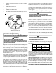
CLEARANCES AND ACCESSIBILITY EXISTING FURNACE REMOVAL Unobstructed front clearance of 24" for servicing is recom- NOTE: When an existing furnace is removed from a venting system serving other appliances, the venting system may be mended. too large to properly vent the remaining attached appliances.
• • • • • • • Drafts, or dead spots behind doors, in corners, or under cabinets. Hot or cold air from registers. Radiant heat from the sun. Light fixtures or other appliances. Radiant heat from a fireplace. Concealed hot or cold water pipes, or chimneys. Unconditioned areas behind the thermostat, such as an outside wall. This furnace must use indoor air for combustion. It cannot be installed as a direct vent (i.e., sealed combustion) furnace.
Vent the furnace in accordance with the National Fuel Gas Code NFPA 54/ANSI Z223.1 - latest edition. In Canada, vent the furnace in accordance with the National Standard of Canada, CAN/CSA B149.1 and CAN/CSA B149.2 - latest editions and amendments. WARNING NEVER ALLOW THE PRODUCTS OF COMBUSTION, INCLUDING CARBON MONOXIDE, TO ENTER THE RETURN DUCTWORK OR CIRCULATION AIR SUPPLY. Venting THIS FURNACE IS NOT DESIGN CERTIFIED TO BE HORIZONTALLY VENTED.
Wash Proper Chimney Termination? (Check 1) Roof Line Clay Tile Size: 8" x 8" x12" (Each x 24" Length) Attic Floor 1/2" to 1" Air Space Second Floor Chimney channel free of solid and liquid fuel appliances? (Check 2) Change venting arrangements (Fix 2) Crown in good condition (Check 3) Rebuild crown (Fix 3) and/or Reline (Fix 4) Cleanout free of debris? (Check 4) Reline (Fix 4) Liner in good condition? (Check 5) Reline (Fix 4) Dilution air available? (Check 6) Reline (Fix 4) Throat Damper Fi
If the chimney does not meet these termination requirements, Appliances which burn propane (sometimes referred to as LP but all other requirements in the checklist can be met, it may (liquefied petroleum)) gas are considered gas-fired appliances. be possible for a mason to extend the chimney. If this will not CHECK 3 - CHIMNEY CROWN CONDITION. be practical, see Fix 1. 10' or Less 2' Min. Damage from condensate usually shows up first in the crown.
Next, use a flashlight and small mirror to sight up the liner. B CHECK 7 - COMPLETE THE INSTALLATION. vent must be supported so as to not come into direct contact with the chimney walls or tile liner. If it is not, it can probably be If Checks 1 through 6 have been satisfactory, and the liner is an rehung so as to be acceptable. A thimble or fire stop may be acceptable size as determined by the tables in National Fuel Gas Code NFPA 54/ANSI Z223.1 - latest edition and in the helpful here.
For sizing of flexible liners, see Note 22 and the tables in the National Fuel Gas Code NFPA 54/ANSI Z223.1 - latest edition If the chimney crown is damaged, a qualified mason must re- and in the National Standard of Canada, CAN/CSA B149.1 and pair it in accordance with nationally recognized building codes CAN/CSA B149.2 - latest editions and amendments. or standards.
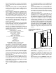
Line voltage connections can be made through either the right or left side panel. The furnace is shipped configured for a right side electrical connection. To make electrical connections through the opposite side of the furnace, the junction box must be relocated to the left side prior to making electrical connections. To relocate the junction box, perform the following steps.
1. Measure resistance between the neutral (white) connection and one of the burners. 2. Resistance should measure 10 ohms or less. R Furnace Integrated Control Module R This furnace is equipped with a blower door interlock switch which interrupts unit voltage when the blower door is opened for servicing. Do not defeat this switch.
To use a single-stage thermostat, turn off power to the furnace, FOSSIL FUEL APPLICATIONS move the thermostat selection DIP switch to the OFF position. Set the desired transition time by setting the transition delay This furnace can be used in conjunction with a heat pump in a DIP switch to the desired ON/OFF position. Turn power back fossil fuel application. A fossil fuel application refers to a combined gas furnace and heat pump installation which uses an on. Refer to the following figure.
HUM-IN HUM-OUT NEUTRAL 24 VOLT HUMIDIFIER A 24 volt humidifier can be powered by feeding one of the HUM terminals with a field installed wire from the R terminal or by connecting to the NO side of the low fire pressure switch. Accessories Wiring If it is necessary for the installer to supply additional line voltage wiring to the inside of the furnace, the wiring must conform to all local codes, and have a minimum temperature rating of 105°C.
NOTE: Do not remove the gas valve inlet plug before the gas This unit is configured for natural gas. The appropriate line is installed. Replace if water or debris has been introduced. manufacturer’s propane gas conversion kit, must be applied for propane gas installations. Refer to the “Propane Gas and/or High Altitude Installations” section for details. INLET GAS SUPPLY PRESSURE Natural Gas Minimum: 4.5" w.c. Maximum: 10.0" w.c. Propane Gas Minimum: 11.0" w.c. Maximum: 13.0" w.c.
• • • • • • • • • Use black iron or steel pipe and fittings for the building piping. Use pipe joint compound on male threads only. Pipe joint compound must be resistant to the action of the fuel used. Use ground joint unions. Install a drip leg to trap dirt and moisture before it can enter the gas valve. The drip leg must be a minimum of three inches long. Install a 1/8" NPT pipe plug fitting, accessible for test gage connection, immediately upstream of the gas supply connection to the furnace.
For satisfactory operation, propane gas pressure must be 10 inch WC at the furnace manifold with all gas appliances in Before placing unit in operation, leak test the unit and gas con- operation. Maintaining proper gas pressure depends on three nections. main factors: 1. Vaporization rate, depending on temperature of the liquid, WARNING and “wetted surface” area of the container or containers. TO AVOID THE POSSIBILITY OF EXPLOSION OR FIRE, NEVER USE A MATCH 2. Proper pressure regulation.
When the furnace is heating, the temperature of the return air entering the furnace must be between 55°F and 100°F. Sizing Between Second Stage and Appliance Regulator* Maximum Propane Capacities listed are based on 2 psig pressure drop at 10 psig setting. Capacities in 1,000 BTU/hour. Pipe or Tubing Length, Feet 10 20 30 40 50 60 80 100 125 150 200 250 Nominal Pipe Size Schedule 40 Tubing Size, O.D.
MINIMUM FILTER SIZES for DISPOSABLE FILTERS FURNACE INPUT (BTU/hr) FILTER SIZE 60K 610 in2 80K 813 in2 100K 889 in2 DISPOSABLE NOMINAL 300 F.P.M. FACE VELOCITY HORIZONTAL INSTALLATIONS Filters must be installed in either the central return register or in the return air duct work.
12. After the burners are lit, set the thermostat to desired temperature. 7. After completion of the 5-minute timer or test mode termination, whichever is earlier, the system will return to normal operation, either continuing an existing heat demand or going to the idle state. FURNACE SHUTDOWN 1. Set the thermostat to the lowest setting. The integrated control will close the gas valve and extinguish flame. Following a 15 second delay, the induced draft blower will be de-energized.
Regulator Vent Gas Valve On/Off Selector Switch High Fire Regulator Adjust Low Fire Regulator Adjust INLET GAS SUPPLY PRESSURE Natural Gas Minimum: 4.5" w.c. Maximum: 10.0" w.c. Propane Gas Minimum: 11.0" w.c. Maximum: 13.0" w.c. If supply pressure differs from table, make the necessary adjustments to pressure regulator, gas piping size, etc., and/or consult with local gas utility. 5. Turn OFF gas to furnace at the manual shutoff valve and disconnect manometer.
3. Calculate the number of seconds per cubic foot (sec/ft3) of gas being delivered to the furnace. If the dial is a one cubic foot dial, divide the number of seconds recorded in step 2 by one. If the dial is a two cubic foot dial, divide the number of seconds recorded in step 2 by two. 4. Calculate the furnace input in BTUs per hour (BTU/hr). Input equals the sum of the installation’s gas heating value and a conversion factor (hours to seconds) divided by the number of seconds per cubic foot.
This furnace is equipped with a multi-speed circulator blower. This blower provides ease in adjusting blower speeds. The Specification Sheet applicable to your model provides an airflow table, showing the relationship between airflow (CFM) and external static pressure (E.S.P.), for the proper selection of heating and cooling speeds. The heating blower speed is shipped set at “B”, and the cooling blower speed is set at “D”.
• 2. Determine the proper air flow for the cooling system. Most cooling systems are designed to work with air flows between 350 and 450 CFM per ton. Most manufacturers recommend an air flow of about 400 CFM per ton. Example: 2.5 tons X 400 CFM per ton = 1000 CFM Profile A provides only an OFF delay of one (1) minute at 100% of the cooling demand airflow. 100% CFM OFF 100% CFM OFF 1 min The cooling system manufacturer’s instructions must be checked for required air flow.
• Profile D ramps up to 50% of the demand for 1/2 minute, then ramps to 85% of the full cooling demand airflow and operates there for approximately 7 1/2 minutes. The motor then steps up to the full demand airflow. Profile D has a 1/2 minute at 50% airflow OFF delay. OFF Sw itch Ban k : S1 Heat OFF Delay 1 2 OFF OFF 120 seconds ON OFF 150 seconds* OFF ON 90 seconds OFF DIP Sw itch No. 180 seconds ON ON (*Indicates f actory setting) Heat Off Delay Dipswitches 7.
the ECM motor. If the outdoor unit or thermostat is responsible for determining the demand, it calculates the demand and transmits the demand along with a fan request to the indoor unit. The indoor unit then sends the demand to the ECM motor. The table below lists the various ComfortNet systems, the operating mode, and airflow demand source.
NOTE: Use of a transformer is recommended if installing a dual COMFORTNET™ SYSTEM ADVANCED FEATURES fuel/fossil fuel system. Failure to use the transformer in the outdoor unit could result in over loading of the furnace transformer. The ComfortNet system permits access to additional system information, advanced setup features, and advanced diagnosCTK0* Thermostat tic/troubleshooting features. These advanced features are or1 2 R C ganized into a menu structure.
FURNACE ADVANCED FEATURES MENUS (ACCESSED THROUGH COMMUNICATING THERMOSTAT) CONFIGURATION Submenu Item Number of Heat Stages (HT STG) Indication (for Display Only; not User Modifiable) Displays the number of furnace heating stages Input Rate (BTU/HR) Motor HP (1/2, ¾, or 1 MTR HP) Displays the furnace input rate in kBtu/hr Displays the furnace indoor blower motor horsepower DIAGNOSTICS Submenu Item Indication/User Modifiable Options Comments Fault 1 (FAULT #1) Fault 2 (FAULT #2) Most rec ent furnace
STATUS Submenu Item Mode (MODE) CFM (CFM) Indication (for Display Only; not User Modifiable) Displays the current furnace operating mode Displays the airflow for the current operating mode NON-COMM (APPLIES ONLY TO A COMMUNICATING COMPATIBLE FURNACE MATCHED WITH A NON-COMMUNICATING COMPATIBLE SINGLE STAGE AIR CONDITIONER) Submenu Item Cool Airflow (CL CFM) User Modifiable Options 18, 24, 30, 36, 42, 48, or 60, default is 18 Comments Selects the airflow for the noncommunicating compatible single stage AC
LED Description Possible Cause Corrective Action Comments Off Normal condition None None None 1 Flash Communications Failure Communications Failure •Depress Learn Button •Verify that bus BIAS and TERM dipswitches are in the ON position.
• Furnace runs, integrated control module monitors safety • R and Y1/G or Y2/G thermostat contacts open, circuits continuously. completing the call for cool. • If the two-stage thermostat changes the call from low • Outdoor fan and compressor are de-energized. • Circulator blower continues running during a cool off delay heat to high heat, the integrated control module will immediately switch the induced draft blower, gas valve, and circulator blower to their high stage settings.
SAFETY CIRCUIT DESCRIPTION A number of safety circuits are employed to ensure safe and proper furnace operation. These circuits serve to control any potential safety hazards and serve as inputs in the monitoring and diagnosis of abnormal function. These circuits are continuously monitored during furnace operation by the integrated control module.
RESETTING FROM LOCKOUT FILTERS Furnace lockout results when a furnace is unable to achieve ignition after three attempts during a single call for heat. It is characterized by a non-functioning furnace and a E 0 code displayed on the dual 7-segment display. If the furnace is in “lockout”, it will (or can be) reset in any of the following ways. 1. Automatic reset. The integrated control module will automatically reset itself and attempt to resume normal operations following a one hour lockout period. 2.
INDUCED DRAFT AND CIRCULATOR BLOWERS BEFORE LEAVING AN INSTALLATION The bearings in the induced draft blower and circulator blower motors are permanently lubricated by the manufacturer. No further lubrication is required. Check motor windings for accumulation of dust which may cause overheating. Clean as necessary. • Cycle the furnace with the thermostat at least three times. Verify cooling and fan only operation.
TROUBLESHOOTING CHART Symptoms of Abnormal Diagnostic/ Status LED Operation (Legacy & Codes ComfortNet™ Thermostat) Fault Description • No 115 power to furnace or no 24 volt power to integrated control module • Blown fuse or circuit breaker • Integrated control module has an internal fault ComfortNet™ Thermostat Only Message Code INTERNAL FAULT EE None None Possible Causes Corrective Actions Notes & Cautions • Manual disconnect switch OFF, door switch open or 24 volt wire improperly connected or
TROUBLESHOOTING CHART Symptoms of Abnormal Operation (Legacy & ComfortNet™ Thermostat) Diagnostic/ Status LED Codes Fault Description ComfortNet™ Thermostat Only Message Code Possible Causes Corrective Actions Notes & Cautions • Induced draft blower runs continuously with no further furnace operation. • Integrated control module LED display provides E2 error code. • ComfortNet™ thermostat “Call for Service” icon illuminated. • ComfortNet™ thermostat scrolls “Check Furnace” message.
TROUBLESHOOTING CHART Symptoms of Abnormal Operation (Legacy & ComfortNet™ Thermostat) Diagnostic/ Status LED Codes Fault Description ComfortNet™ Thermostat Only Possible Causes Message Code IGNITER FAULT E7 • Improperly connected igniter. • Shorted igniter. • Poor unit ground. • Igniter relay fault on integrated control module. Corrective Actions Notes & Cautions • Furnace fails to operate. • Integrated control module LED display provides E7 error code.
TROUBLESHOOTING CHART Symptoms of Abnormal Diagnostic/ Operation (Legacy Status LED Fault Description & ComfortNet™ Codes Thermostat) ComfortNet™ Thermostat Only Message Code Possible Causes Corrective Actions Notes & Cautions • Operation different than expected or no operation. • Integrated control module LED display provides d4 error code. • ComfortNet™ thermostat “Call for Service” icon illuminated. • ComfortNet™ thermostat scrolls “Check Furnace” message. d4 • Invalid memory card data.
TROUBLESHOOTING CHART Symptoms of Abnormal Diagnostic/ Operation (Legacy Status LED Fault Description & ComfortNet™ Codes Thermostat) • Furnace fails to operate. • Integrated control module LED display provides b4 error code. • ComfortNet™ thermostat “Call for Service” icon illuminated. • ComfortNet™ thermostat scrolls “Check Furnace” message. b4 • Furnace fails to operate. • Integrated control module LED display provides b5 error code. • ComfortNet™ thermostat “Call for Service” icon illuminated.
STATUS CODES INTERNAL CONTROL FAULT/NO POWER O n E 0 E 1 NORMAL OPERATION E 2 LOW STAGE PRESSURE SWITCH STUCK OPEN E 3 E 4 OPEN HIGH LIMIT SWI TCH E 5 OPEN FUSE E 6 LOW FLAME SIGNAL E 7 IGNITER FAULT OR IMPROPER GROUNDING E 8 HIGH STAGE PRESSURE SWITCH STUCK CLOSED AT START OF HEATING CYCLE E 9 E A E F d 0 d 4 HIGH STAGE PRESSURE SWITCH STUCK OPEN b b b b 0 1 2 LOCKOUT DUE TO EXCESSIVE RETRIES LOW STAGE PRESSURE SWITCH STUCK CLOSED AT START OF HEATING CYCLE FLAME DETECTED WHEN NO FLAME S
AIR FLOW DATA Speed Selection Dip Switches Cool Selection Switches TAP Adjust Selection Switches Profile Selection Switches S3- 1 S3- 2 S3- 3 S3- 4 S4-1 S4-2 Model Heat Selection Switches 735 805 875 945 1050 1150 1250 1350 *DVC80805C*** A B C D 520 715 910 1170 800 1100 1400 1800 945 1015 1085 1155 1350 1450 1550 1650 60 sec/100% *DVC81005C*** A B C D 553 748 943 1203 850 1150 1450 1850 1085 1155 1225 1260 1550 1650 1750 1800 *MVC80604B*** A B C D 390 520 715 910 600 800 1100 1400
DIP SWITCHES Switch Bank Purpose Heating Off Delay S1 Thermostat Setup Cooling Airflow S3 Trim Ramping Profile S4 Heating Airflow Dehum Trim S5 Continuous Fan Function 90 120 150 180 2 Stage Stat 2 Stage Stat 1 Stg Stat 5 min delay 1 Stg Stat auto delay A B C D Add 5% Minus 5% Add 10% Minus 10% A B C D A B C D Disabled Enabled Disabled Enabled 25% 50% 75% 100% 47 1 Off On Off On Off On Off On Off On Off On Dip Switch 2 3 Off Off On On On On Off Off Off Off On On Off On Off On Off Off On On Off On
*MVC8, *DVC8 WHITE RODGERS GAS VALVE WIRING DIAGRAM TO 115 VAC/ 1 Ø /60 HZ POWER SU PPLY WITH OVERCURRENT PROTECTION DEVICE GND 24V HUM.
*MVC8, *DVC8 HONEYWELL GAS VALVE WIRING DIAGRAM TO 115 VAC/ 1 Ø /60 HZ POWER SUPPLY WITH OVERCURRENT PROTECTION DEVICE GND C BK WH 2 PM 1 DISCONNECT TO 115VAC/ 1 Ø /60 HZ POWER SUPPLY WITH OVERCURRENT PROTECTION DEVICE YL WARNING: DISCONNECT POWER BEFORE SERVICING. WIRING TO UNIT MUST BE PROPERLY POLARIZED AND GROUNDED.
THIS PAGE LEFT INTENTIONALLY BLANK 50
THIS PAGE LEFT INTENTIONALLY BLANK 51
Our continuing commitment to quality products may mean a change in specifications without notice. © 2013-2014 5151 San Felipe St., Suite 500, Houston, TX 77056 www.daikincomfort.