
Installation Instructions Comfort Bridge Models

13
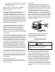
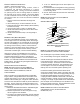
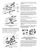
terMInatIon locatIons
Non-Direct Vent
Vent/Flue Termination
No Terminations
Above Walkway
Non-Direct Vent
Vent/Flue Termination
Direct Vent
Vent/Flue Termination
Forced Air
Inlet
Non-Direct Vent
&
Direct Vent
Vent/Flue Terminations
Grade or Highest
Anticipated
Snow Level
Vent clearances
fIgure 7
note: refer to locatIon requIrements and
consIderatIons for coMBustIon aIr contaMInant
restrIctIons.
The following bullets and diagram describe the restrictions
concerning the appropriate location of vent/ue pipe and
combustion air intake pipe (when applicable) terminations.
Refer to Non-Direct Vent (Single Pipe) Piping and Direct
Vent (Dual Pipe) Piping located in this section for specic
details on termination construction.
• All terminations (ue and/or intake) must be located at
least 12 inches above ground level or the anticipated
snow level.
• Vent terminations (non-direct and direct vent) must
terminate at least 3 feet above any forced air inlet
located within 10 feet.
note: tHIs ProVIsIon Does not aPPlY to tHe
coMBustIon aIr Intake terMInatIon of a DIrect Vent
aPPlIcatIon.
• The vent termination of a non-direct vent application
must terminate at least 4 feet below, 4 feet
horizontally from, or 1 foot above any door, window, or
gravity air inlet into any building.
• The vent termination of a direct vent application must
terminate at least 12 inches from any opening through
which ue gases may enter a building (door, window,
or gravity air inlet).
• The vent termination of vent pipe run vertically
through a roof must terminate at least 12 inches
above the roof line (or the anticipated snow level) and
be at least 12 inches from any vertical wall (including
any anticipated snow build up).
• A vent termination shall not terminate over public
walkways or over an area where condensate or
vapor could create a nuisance or hazard or could
be detrimental to the operation of regulators, relief
valves, or other equipment.
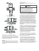
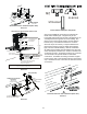
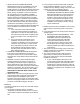
TRANSITION NO LESS
THAN 45 DEGREES TO
HORIZONTAL PLANE TO
AVOID CREATING A WATER
TRAP IN VENT PIPING.
ACCEPTABLE
fIgure 5
NO TRANSITION ON
HORIZONTAL PLANE,
THIS CREATES A
WATER TRAP AND
RESTRICTS FLUE
GASES
fIgure 6
Some models require the use of 3” pipe. Do not transition
from a 2” to 3” pipe in a horizontal section of pipe as this
may create a water trap.
Piping must be adequately secured and supported to
prohibit sagging, joint separation, and/or detachment from
the furnace. Horizontal runs of vent/ue piping must be
supported every three to ve feet and must maintain a 1/4
inch per foot downward slope, back towards the furnace, to
properly return condensate to the furnace’s drain system.
Allowances should be made for minor expansion and
contraction due to temperature variations. For this reason,
particular care must be taken to secure piping when a long
run is followed by a short offset of less than 40 inches.
Precautions should be taken to prevent condensate from
freezing inside the vent/ue pipe and/or at the vent/ue
pipe termination. All vent/ue piping exposed to freezing
temperatures below 35°F for extended periods of time
must be insulated with 1/2” thick closed cell foam. Also
all vent/ue piping exposed outdoors in excess of the
terminations shown in this manual (or in unheated areas)
must be insulated with 1/2” thick closed cell foam. Inspect
piping for leaks prior to installing insulation.