
Installation Instructions Comfort Bridge Models

17
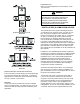
4. 2 1/2” or 3” diameter pipe can be used in place of 2”
diameter pipe.
5. Increased Clearance Congurations using (2) 45 deg.
Long Sweep elbows should be considered equivalent
to one 90 deg. elbow.
6. One 90° elbow should be secured to the combustion
air intake connection.
note: for InstallatIons at or aBoVe 7,000 feet
altItuDe, use 3” VentIng.
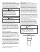
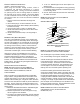
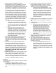
Vent/flue PIPe terMInatIons
12" MIN.
VENT/FLUE TEE (
or
45° ELBOW
TURNED DOWN or
90° ELBOW TURNED
DOWN
OPTIONAL)
HorIZontal terMInatIon (sIngle PIPe)
aBoVe HIgHest antIcIPateD snow leVel
fIgure 12
note: If eItHer a 90 Degree or 45 Degree elBow Is
useD for terMInatIon, It Must Be PoInteD DownwarD.
The vent/ue pipe may terminate vertically, as through a
roof, or horizontally, as through an outside wall.
Vertical vent/ue pipe terminations should be as shown
in the following gure. Refer to Vent/Flue Pipe and
Combustion Air Pipe - Termination Locations for details
concerning location restrictions. The penetration of the
vent through the roof must be sealed tight with proper
ashing such as is used with a plastic plumbing vent.
Horizontal vent/ue pipe terminations should be as
shown in the following gure. Refer to Vent/Flue Pipe and
Combustion Air Pipe. To secure the pipe passing through
the wall and prohibit damage to piping connections, a
coupling should be installed on either side of the wall and
solvent cemented to a length of pipe connecting the two
couplings. The length of pipe should be the wall thickness
plus the depth of the socket ttings to be installed on the
inside and outside of the wall. The wall penetration should
be sealed with silicone caulking material.
note: terMInate BotH PIPes In tHe saMe Pressure
Zone (saMe sIDe of roof, no Major oBstacles
Between PIPes, etc.).
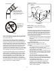
a
lternate coMBustIon aIr ProVIsIon
(Upow / Horizontal models only)
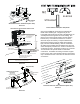
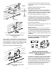
When using the alternate venting location, either in
a horizontal left side down installation or a vertical
installation using down – venting, an alternate combustion
air opening can be used. A locating dimple is located on
the right side of the furnace cabinet. The locating dimple
is 1 7/8” measured from the front edge of the cabinet in
line with the knock out. To use the alternate combustion
air location:
1. Remove screws and combustion air ange from
cabinet.
2. Insert cabinet plug in unused combustion air hole.
3. Drill a pilot hole at the cabinet dimple (size dictated by
knockout tool used).
4. Use a knockout tool to create a 3” diameter hole.
5. Install combustion air ange and secure with screws
removed in step one.
6. Install screws removed in step 1 securing ange to
cabinet.
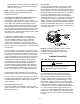
non-DIrect Vent (sIngle PIPe) PIPIng
Non-direct vent installations require only a vent/ue pipe.
The vent pipe can be run horizontally with an exit through
the side of the building or run vertically with an exit through
the roof of the building. The vent can also be run through
an existing unused chimney; however, it must extend a
minimum of 12 inches above the top of the chimney. The
space between the vent pipe and the chimney must be
closed with a weather-tight, corrosion-resistant ashing.
Although non-direct vent installations do not require a
combustion air intake pipe, a minimum of one 90° elbow
should be attached to the furnace’s combustion air
intake if: an upright installation uses the standard intake
location, or a horizontal installation uses the alternate air
intake location. This elbow will guard against inadvertent
blockage of the air intake.
Vent/flue PIPe lengtHs anD DIaMeters
note: for InstallatIons at or aBoVe 7,000 feet
altItuDe, use 3” VentIng. If eItHer a 90 Degree or 45
Degree elBow Is useD for terMInatIon, It Must Be
PoInteD DownwarD.
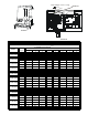
Refer to the table on the preceding page for applicable
length, elbows, and pipe diameter for construction of the
vent/ue pipe system of a non-direct vent installation. In
addition to the vent/ue pipe, a single 90° elbow should be
secured to the combustion air intake to prevent inadvertent
blockage. The tee used in the vent/ue termination must
be included when determining the number of elbows in the
piping system.
1. Maximum allowable limits listed on individual lengths
for inlet and ue and NOT a combination.
2. Minimum requirement for each vent pipe is ve (5)
feet in length and one elbow/tee.
3. Tee used in the vent/ue termination must be included
when determining the number of elbows in the piping
system.